More Textures!

This’ll be a short update. I came up with a better pavement texture, and, while trying for the stones, came up with a nice method of star generation, so I refined that as well. Hooray for happy accidents!

The stars one really looks best zoomed in (the thumbnail looks kinda lame), but I like them both!


Click to enlarge

All 100% pixel-shader generated. Both of these use pure improved perlin noise modifications to generate their look…no custom patterns like the brick and tile textures from earlier.

If you want to play around with the generator, the binary, code, and shaders are in a zip in the previous post. Have at it and let me know if you make anything awesome!

Procedual Terseness

The Most Communicative Of Fingers

This entry was going to be a bit longer, but:

OWW MY LMF ASPLODE!

Yeah. It’s the classic tale of “boy meets girl, girl rejects boy,” except you replace “boy” with “finger,” “girl” with “wall,” and “rejects” with “breaks.”

Sometimes playing wallyball can be considered dangerous.

Procedural Textures

As part of the framework for the game I am currently writing, I’m going to have as much texture data as possible be procedural and cached in on the fly. There are a few reasons for this choice (many of which should be obvious):

  • Less disk usage – very useful if I hit my target of, oh, say, a certain game console
  • Non-repeating textures – textures don’t have to tile. I can keep caching in new ones.
  • Seriously, I suck at texture art – This way, the computer does it for me!

I’m still working on the method, but here are a few examples:


Click to enlarge

These are all generated on-GPU, using ps_3_0 shaders. The noise implementation comes straight (thank you, copy-and-paste) from GPU Gems 2, which is an awesome book.

The idea is that objects (especially static world objects) will have unwrapped UV coordinates (like you’d use for lightmaps). To generate the textures onto the objects, I’ll do the following:

  1. Create a texture that is the requisite size (or pull it out of a pool, which is more likely
  2. Render the objects into the texture, using the UV coordinates as the position (scaled from [0,1] to [-1,1] of course).
  3. Pass the position and/or normal to the pixel shader, use it to generate the texture data
  4. Repeat for as many textures as the object needs (some combination of diffuse color, normal, height, glossiness, etc).

Should be pretty easy. Obviously, there are some patterns that are ridiculously difficult or even maybe impossible to generate efficiently on the GPU, so I’ll probably still use some pre-made texturemaps. But as much as I possibly can do on the GPU, I will. The main gotcha will be keeping the amount of texture info that needs to be generated to a minimum, so there aren’t any render stalls. That’s more of a level design/art problem though (which, because this is being developed lone-wolf, is also my problem).

If you want to see the shaders I’ve used and the code that I used, here is my sample app (with full source):

ProcTexGen.zip – 29KB.

The source is ridiculously uncommented because I coded it over the span of maybe 3 hours as a quick prototype, and the shaders are, I’m sure, nowhere near efficient. Also, they don’t handle negative values very well, which is why many of them add 100 to the coordinates (HACKHACKHACK).

Enjoy! And if you make any awesome textures with it, please let me know 🙂

D3D10 + Deferred Shading = MSAA!

For the last few days I’ve been working at learning D3D10 and using it to whip up a quick prototype of doing fully-deferred shading while using MSAA (multisample antialiasing). If you’re not sure what deferred shading is, but are curious, check out the deferred shading paper at NVIDIA’s developer site. Here are my notes on the experience.

On D3D10

D3D10 is very, very well-designed. It has some interesting new bits of functionality, but the way that the API has been rearranged is really quite nice, though it does tend to produce MUCH more verbose code.

One thing in particular that is very different is the buffer structure. rather than creating a buffer of a specific type (IDirectDrawVertexBuffer9, etc), you simply create a generic buffer (ID3D10Buffer). When you create a buffer, you specify the flags with which it can be bound (as a vertex buffer, index buffer, render target, constant buffer [another new feature], etc).

For instance, here’s my helper function to create a vertex buffer:

HRESULT CreateVertexBuffer(void *initialData, DWORD size, ID3D10Buffer** vb)
{
  D3D10_BUFFER_DESC bd;
  bd.Usage = D3D10_USAGE_IMMUTABLE; //  This tells it that the buffer will be filled with data on initialization and never updated again.
  bd.ByteWidth = size;
  bd.BindFlags = D3D10_BIND_VERTEX_BUFFER; // This tells it that it will be used as a vertex buffer
  bd.CPUAccessFlags = 0;
  bd.MiscFlags = 0;

  // Pass the pointer to the vertex data into the creation
  D3D10_SUBRESOURCE_DATA vInit;
  vInit.pSysMem = initialData;

  return g_device->CreateBuffer( &bd, &vInit, vb);
}

It’s pretty straightforward, but you can see that it’s a tad more verbose than a single-line call to IDirect3DDevice9::CreateVertexBuffer.

Another thing that I really like is the whole constant buffer idea. Basically, when passing state to shaders, rather than setting individual shader states, you build constant buffers, which you apply to constant buffer slots (15 buffer slots that can hold 4096 constants each – which adds up to a crapton of constants). So you can have different constant blocks that you can Map/Unmap (the D3D10 version of Lock/Unlock) to write data into, and you can update them based on frequency. For instance, I plan to have a cblocks that are per-world, per-frame, per-material, and per-object.

But the feature that’s most relevant to this project is this little gem:
You can read individual samples from a multisample render target.
This is what allows you to do deferred shading with true multisample anti-aliasing in D3D10.

The only thing that really, really sucks about D3D10 is the documentation. It is missing a lot of critical information, some of the function definitions are wrong, sample code has incorrect variable names, etc, etc. It’s good at giving a decent overview, but when you start to drill into specifics, there’s still a lot of work to be done.

SV_Position: What Is It Good For (Absolutely Lots!)

SV_Position is the D3D10 equivalent of the POSITION semantic: it’s what you write out of your vertex shader to set the vertex position.

However, you can also use it in a pixel shader. But what set of values does it contain when it reaches the pixel shader? The documentation was (unsurprisingly) not helpful in determining this.

Quite simply, it gives you viewport coordinates. That is, x and y will give you the absolute coordinates of the current texel you’re rendering in the framebuffer (if your framebuffer is 640×480, then a SV_Position.xy in the middle would be (320×240)).

The Z coordinate is a viewport Z coordinate (if your viewport’s MinZ is 0.5 and your MaxZ is 1, then this z coordinate will be confined to that range as well).

The W coordinate I’m less sure about – it seemed to be the (interpolated) w value from the vertex shader, but I’m not positive on that.

I thought this viewport-coordinate thing was a tad odd…I mean, who cares which absolute pixel you’re at on the view? Why not just give me a [0..1] range? As it turns out, when sampling multisample buffers, you actually DO care, because you don’t “sample” them. You “load” them.

Doing a texture Load does not work quite like doing a texture Sample. Load takes integer coordinates that correspond to the absolute pixel value to read. Load is also the only way to grab a specific sample out of the pack.

But, in conjunction with our delicious SV_Position absolute-in-the-render-target coordinates, you have exactly the right information!

Pulling a given sample out of the depth texture is as easy as:

int sample; // this contains the index of the sample to load.  If this is a 4xAA texture, then sample is in the range [0, 3].
VertexInput i; // i.position is the input SV_Position.  It contains the absolute pixel coordinates of the current render.
texture2DMS<float, NUMSAMPLES> depthTexture; // This is the depth texture - it's a 2D multi-sample texture, defined as
                                             // having a single float, and having NUMSAMPLES samples

// Here's the actual line of sampling code
float  depth   = depthTexture.Load(int3((int2)i.position.xy, 0), sample).x;

Simple! I do believe it is for exactly this type of scenario (using Load to do postprocess work) that SV_Position in the PS was designed the way it is. Another mystery of the universe solved. Next on the list: “What makes creaking doors so creepy?”

Workin’ It

Simply running the deferred algorithm for each sample in the deferred GBuffers’ current texel and averaging them together works just fine. That gets you the effect with a minimum of hassle. But I felt that it could be optimized a bit.

The three deferred render targets that get used in this demo are the unlit diffuse color buffer (standard A8R8G8B8), the depth render (R32F), and the normal map buffer (A2R10G10B10). The depth render is not necessary in D3D10 when there is no multisampling, because you can read from a non-ms depth buffer in D3D10. However, you can’t map a multisampled depth buffer as a texture, so I have to render depth on my own.

Anyway, I wanted to have a flag that denoted whether or not a given location’s samples were different or not. That is, if it’s along a poly edge, the samples are probably different. But, due to the nature of multisampling, if a texel is entirely within a polygon’s border, all of the samples will contain the same data. There is really no need to do deferred lighting calculations on MULTIPLE samples when one would do just fine. So I added a pass that runs through each pixel and tests the color and depth samples for differences. If there ARE differences, it writes a 1 to the previously-useless 2-bit alpha channel in the normal map buffer. Otherwise, it writes a 0.

What this does, is allows me to selectively decide whether to do the processing on multiple samples (normalMap.w == 1) or just a single one (normalMap.w == 0).

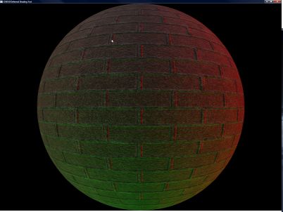
Here is a visualization:
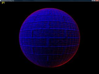

Click to enlarge

I’ve tinted it red where extra work is done (the shading is done per-sample) and blue where shading is only done once.

This didn’t have the massive performance boost that I was expecting – I figured having a single pass through almost all samples then only loading them as-needed would save massive amounts of texture bandwidth during the lighting phase, as well as cutting down on the processing.

I was half-right.

In fact, the performance boost was much smaller than expected. The reason is, I’ve guessed, is that when caching the multisample texture, it caches all of the samples (because it’s likely that they’ll all be read under normal circumstances), so it really doesn’t cut down on the memory bandwidth at all. What it DOES cut down on is the processing which, as the lighting gets more complex (shadowing is added, etc), WILL become important. Also, since my shader is set up to be able to do up to 8 lights in a single pass, It renders 25 full-scene directional lights (in…4 passes) at about 70fps with 4xAA at 1280×964 (maximized window, so not the whole screen) on my 8800GTX. As a comparison, it’s about 160 fps without the AA.

With a more reasonable 4 lights (single-pass) it’s 160fps at that resolution with AA, and 550 without. Not bad at all!

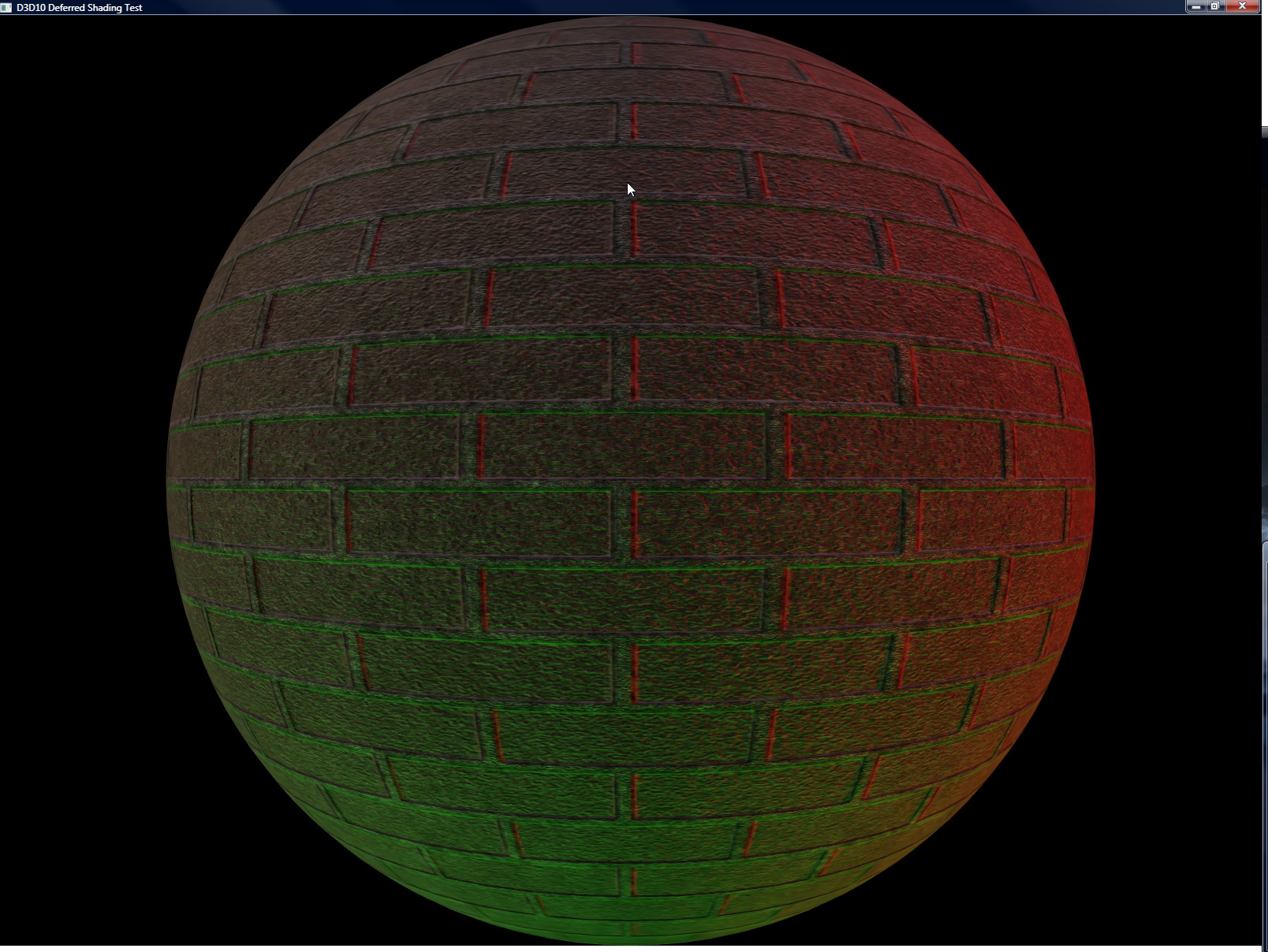
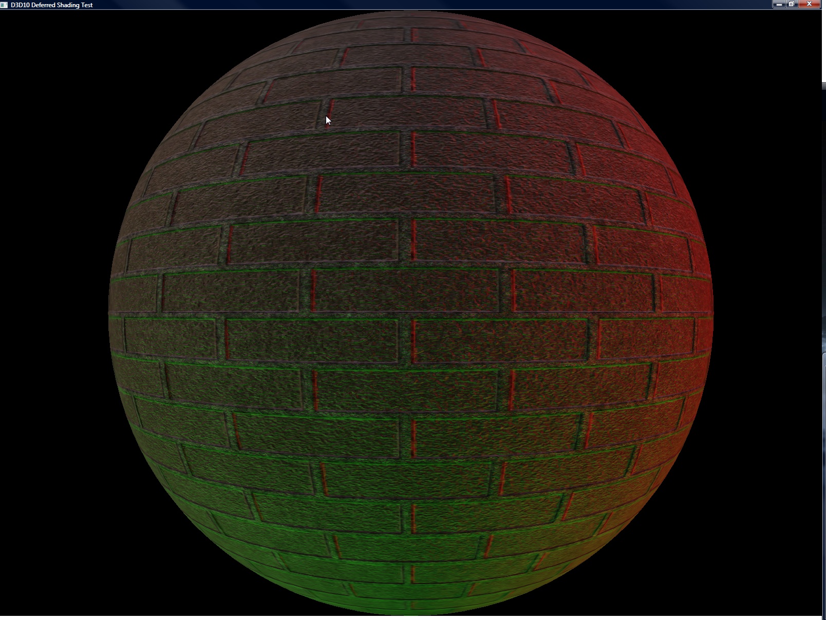
Here are two screenshots, one with AA, one without (respectively). Note that they look exactly the same in thumbnails. I could have probably used the same thumbnail for them, but whatever 🙂


Click to enlarge

And here it is!

Crappy D3D10 Deferred-with-AA demo (with hideous, hideous source!)

Pressing F5 will toggle the AA on and off (it just uses 4xAA). It defaults to off.

WTS: Plane of +1 Infinity

So I finally got something interesting working. While there’s no pretty shading or even eye candy, what there IS is an infinite plane renderer, using a grid. The idea was to use this for water rendering, but there’s an easier and less complicated way to do it (a la Far Cry) that I’m going to use instead. I just thought I’d finish this up anyway because it’s moderately novel (at least, to me. Maybe it’s not.)
A few pictures of it in action (Hooray for poorly-compressed JPGs and their many artifacts!):


Click to Enlarge

What makes this interesting (to me at least, if nobody else) is that the visible portions of the plane are (for the most part) the whole visible bit of the plane. Also, the grid spacing is interpolated in post-projection space, so it’s a constant-ish LOD across the screen (which was to be a great help in rendering water waves with the detail in the near waves, but not the far waves).
Here are some pictures of it with the gridlines:


Click to Enlarge

Advantages:

  • With the exception of the four 4-component vectors used as shader constants, nothing is transferred to the card on a per-frame basis. The vertex/index buffers are completely static.
  • A very minimum of the grid is off-screen. Thus, the transformations are reserved for the on-screen objects only
  • With the screen-space linear interpolation of the grid, detail is concentrated where it’s needed.

Disadvantages:

  • Complex. Finding the best four points for the on-screen representation of the grid wasn’t quite as easy as I had initially thought. Especially since there are 5 and 6 edge cases.
  • The vertex shader is ever-so-slightly more complex than a normal shader. Just a few instructions, but every little bit, right?
  • It actually is quite difficult to make it handle the variations in height necessary for a water wave renderer. Actually, I haven’t done that part yet (and since I’ve found an easier way of doing the same thing, I probably won’t). That is left as an exercise for the reader.

How does it work, you ask? Okay, nobody asked that, but I’m going to tell you anyway. Because that’s what I do.

First up is the on-CPU setup. Given a plane in the 4-vector form of [a, b, c, d] (i.e. ax + by + cz +d = 0)

  1. Project the plane into post-projection space. To transform a plane using the 4×4 transformation matrix T, you multiply the 4-vector plane representation by the matrix Transpose(Inverse(T)). I decided to do the plane clipping in post-projection space because the clipping against the frustum is easier there (as it’s a box instead of a sideways headless pyramid).
  2. Get the vertices of the intersection between the frustum and the plane.
    • This intersection is the intersection of three planes: The two planes making up the frustum side, and the plane being rendered. However, since the planes of the frustum are axis-aligned planes in post-projection space, this can be simplified by substituting in the two known components (from the frustum planes) for that edge and solving for the third variable. For instance given the upper-left corner (x = -1, y = -1), z = -(a*x + b*y + d)/c.
    • Once you have the third component, check to make sure that it is within the valid half-cube range (Note: in Direct3D, visible post-perspective space is within the half-cube where x is in [-1, 1], y is in [-1, 1] and z is in [0, 1]). If it IS in range, add it to the list of edge points.
    • There can be at most six points generated by this set of checks (giving one polygonal edge per frustum plane. 6 edges = 6 points, see?)
  3. Ensure a clockwise winding order for the points. I used the gift-wrap sort of method, starting at the point nearest the screen, do a 2D check (ignore Z) to find the “most clockwise” point along the way (i.e. the point at which, given the line between the current point and the next point, all vertices are to the right of that line).
  4. This is the complicated part. We need to get the number of points to exactly 4 (as what the shader is expecting is a quad)
    • Given 3 points, duplicate the one nearest the camera.
    • Given 5 points:
      • Find the diagonal edge that crosses from one side to an adjacent side (i.e crosses from the top side to the right side, as opposed to left to right)
      • Look at the intersection between that diagonal line and the two sides that it currently doesn’t touch.
      • Choose the side that has the intersection point nearest the screen, and extend the corresponding point along the diagonal to the intersection point
      • At that point, along the edge where that intersection was, there are now three collinear points. Remove the one in the middle, which brings the total down to four points
    • Given 6 points:
      • There are two diagonals that cross from one side to an adjacent one, so we’ll pick the one that represents the far plane intersection (the z coordinate of both of the points on this diagonal will be 1).
      • That diagonal gets extended to both of the sides that it doesn’t touch, similar to the 5-point case. Except that it extends both directions instead of just the one.
      • Remove the two redundant vertices
  5. Send the 4 points to GPU (I pass them in in the world matrix slot, since they’re 4 float4 values).

Okay, that was the worst of it. Now there’s the GPU-side bits:

  1. The mesh input is a grid of u,v coordinates ranging from 0 to 1. Linearly interpolate between the four post-projective planar intersection points passed in from the CPU using the u,v values. worldSpace = lerp(lerp(inMatrix[0], inMatrix[1], in.u), lerp(inMatrix[3], inMatrix[2], in.u), in.v) The 3 and 2 are in that order because the vertices are given in clockwise order.
  2. Using the inverse viewproj matrix, project these points back into worldspace.
  3. The worldspace x and z can be used as texture coordinates (scaled, if you want. I use them verbatim right now).
  4. Reproject the worldspace coordinates back into projected space. This is necessary because the linearly interpolated points are not perspective-correct (causing the texture mapping to totally flip out. It was like a bad flashback to the original Playstation. I do not wish that upon others).

Math-heavy? Yep.
Poorly explained in this post? Probably.
Able to be cleared up by questions in the comments section? You betcha.

Hope this has been informative (though it’s more of a dry read than I would have liked).