One Pass, Two Pass, Red Pass, Blue Pass

Here it is: another late-week journal update that pretty much chronicles my weekend accomplishments, only later.

But First, Beams!

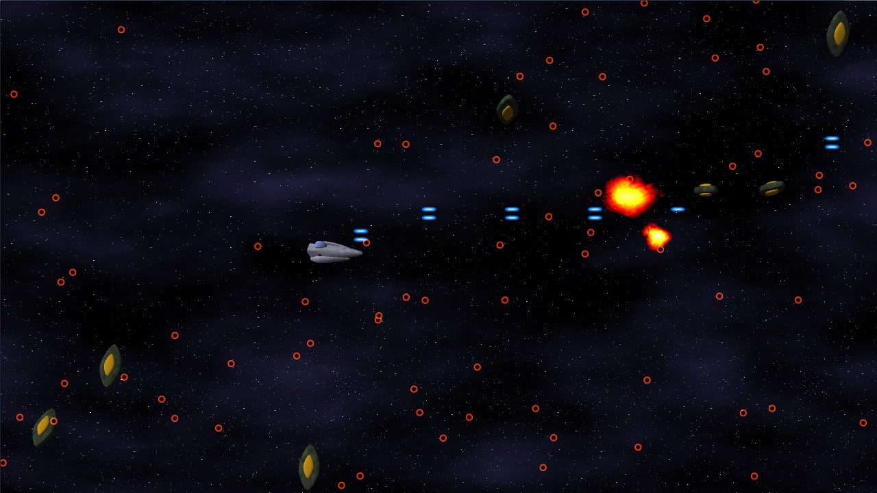
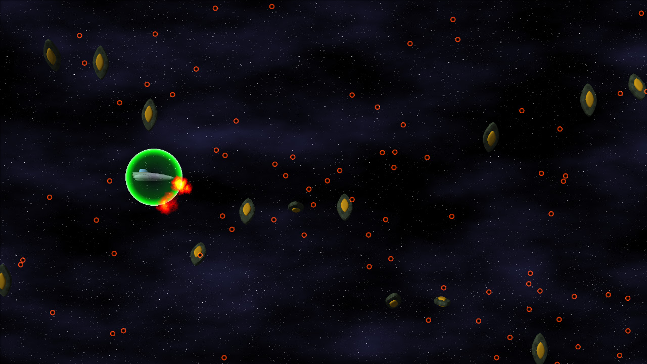
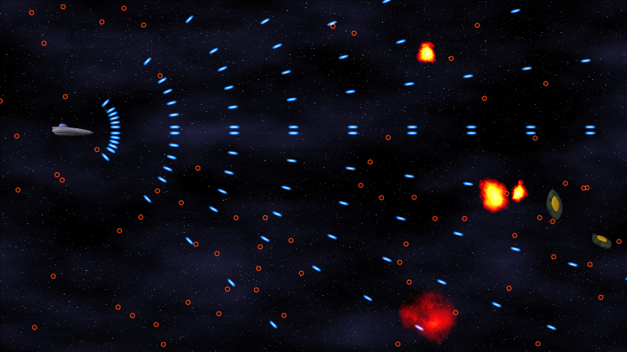
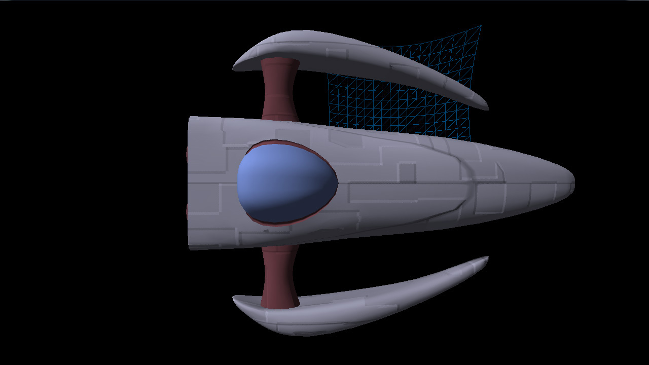
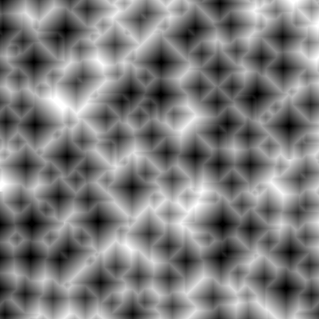
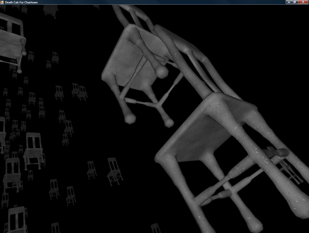
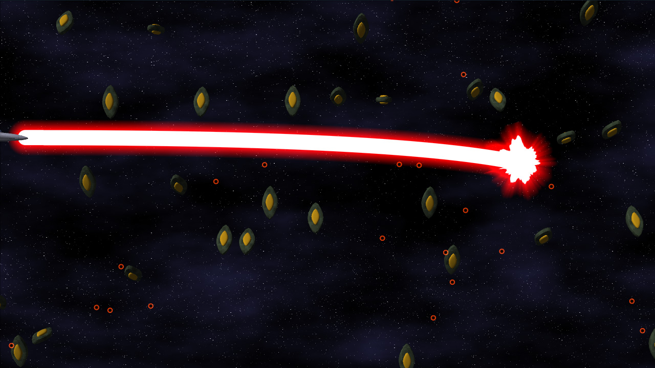
First up, here’s a preview of the powered-up version of the final main weapon for the project:


Click to enlarge

The beam itself actually locks on to targets and continually damages them. Implementation-wise, it’s a quadratic bezier. Initially, I tried to calculate the intersection of a quadratic-bezier-swept sphere (i.e. a thick bezier curve) and a bounding sphere exactly. That’s all great, only it becomes a quartic equation (ax^4 + bx^3 + cx^2 + dx + e == 0), which is ridiculously difficult to compute programmatically (just check the javascript source on this page to see what I mean). So I opted for another solution:

I divided the curve up into a bunch of line segments, treated those segments as sphere-capped cylinders (capsules), and did much simpler intersection tests. PROBLEM SOLVED!

When Is Deferred Shading Not Deferred Shading?

I also implemented Light Pre-Pass Rendering, which is sort of a “Low-Calorie Deferred Shading” that Wolfgang Engel devised recently. Considering my original plan for lighting was to only allow right around 3 lights on-screen at a time, this gives me a much greater range of functionality. It’s a three-step process, as illustrated below.

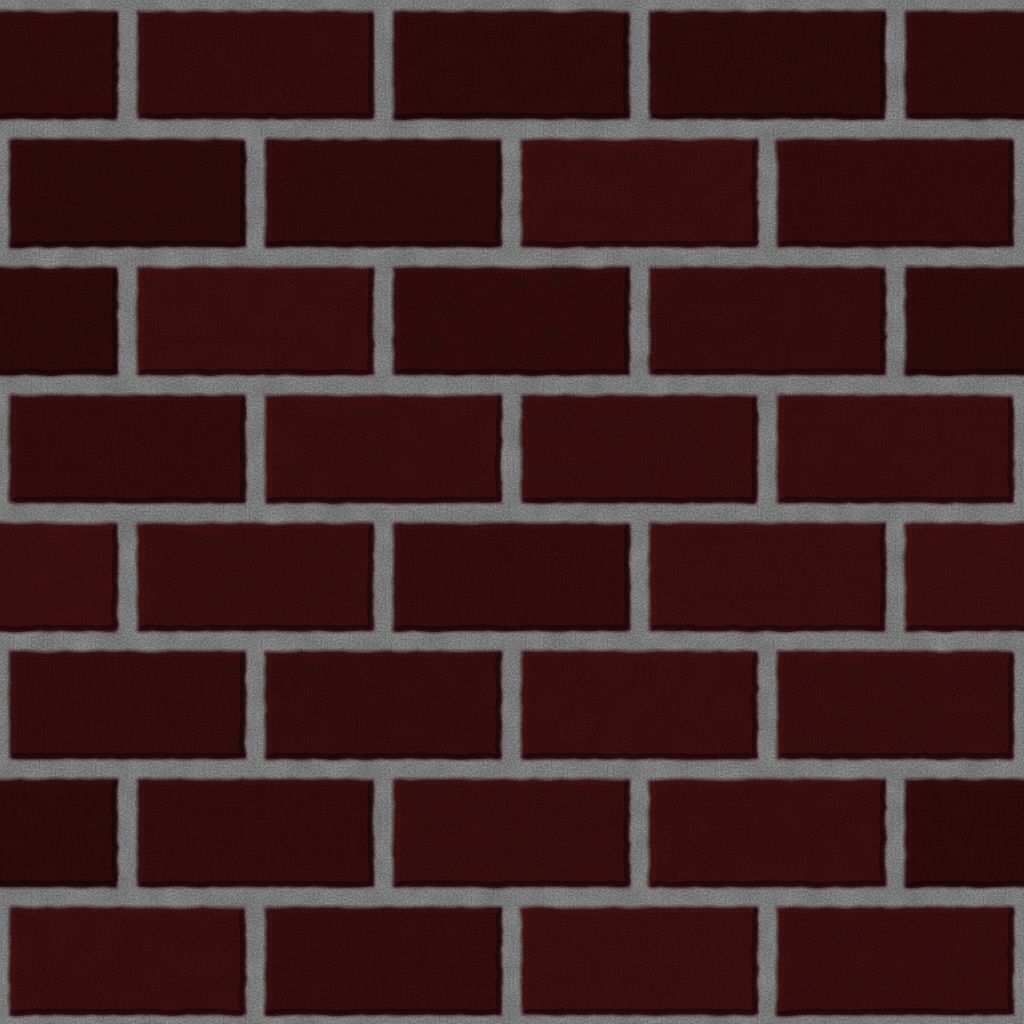
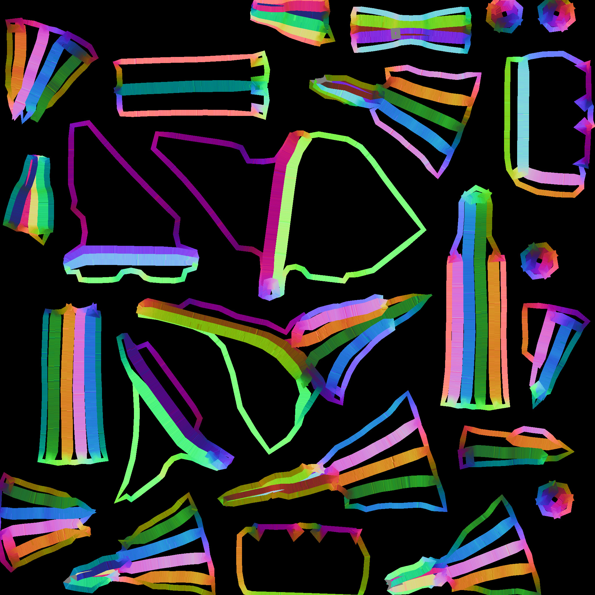
Render Object Normals (Cut a hole in a box)

Step 1: render all of the objects’ normals and depth to a texture. Due to limitations that are either related to XNA or the fact that I want to allow a multisampled buffer, I’m not sure which, I can’t read from the depth buffer, so I have to render the object depth into the same texture that the normal map is rendering into.

Given two normal components, you can reconstruct the third (because the normal’s length is one). Generally, Z is used on the assumption that the Z component of the normal is always pointing towards the screen. However, with bump mapping (and even vertex normals), this is not a valid assumption. So just having the X and Y normal components is not enough. I decided to steal a bit from the blue channel to store the SIGN of the Z component. This leaves me with 15 bits of Z data, which, given the very limited (near-2D) range of important objects in the scene, is more than plenty for the lighting (as tested by the ugly-yet-useful “Learning to Love Your Z-Buffer” page).

Consequently, the HLSL code to pack and unpack the normals and depth looks like this:

float4 PackDepthNormal(float Z, float3 normal)
{
  float4 output;

  // High depth (currently in the 0..127 range
  Z = saturate(Z);
  output.z = floor(Z*127);

  // Low depth 0..1
  output.w = frac(Z*127);

  // Normal (xy)
  output.xy = normal.xy*.5+.5;

  // Encode sign of 0 in upper portion of high Z
  if(normal.z < 0)
    output.z += 128;

  // Convert to 0..1
  output.z /= 255;

  return output;
}

void UnpackDepthNormal(float4 input, out float Z, out float3 normal)
{
  // Read in the normal xy
  normal.xy = input.xy*2-1;

  // Compute the (unsigned) z normal
  normal.z = 1.0 - sqrt(dot(normal.xy, normal.xy));
  float hiDepth = input.z*255;

  // Check the sign of the z normal component
  if(hiDepth >= 128)
  {
    normal.z = -normal.z;
    hiDepth -= 128;
  }

  Z = (hiDepth + input.w)/127.0;;
}

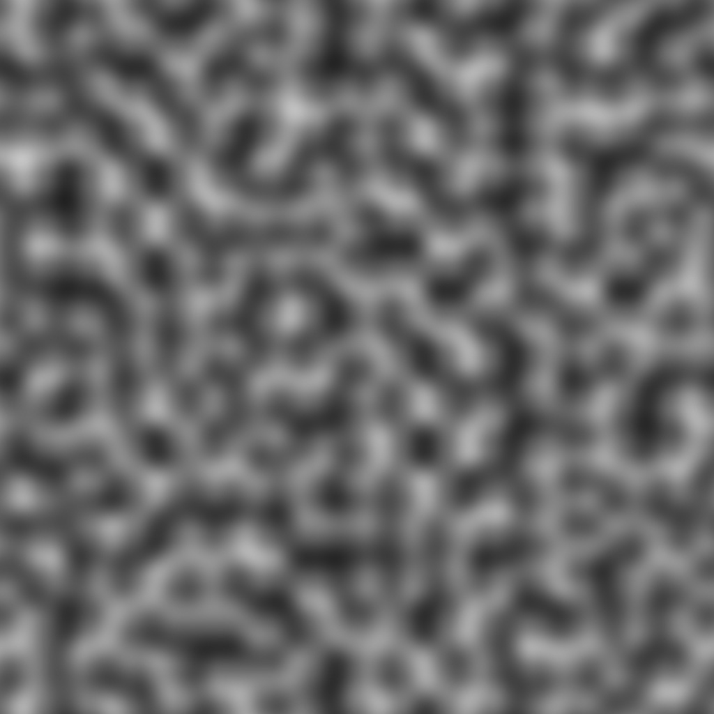
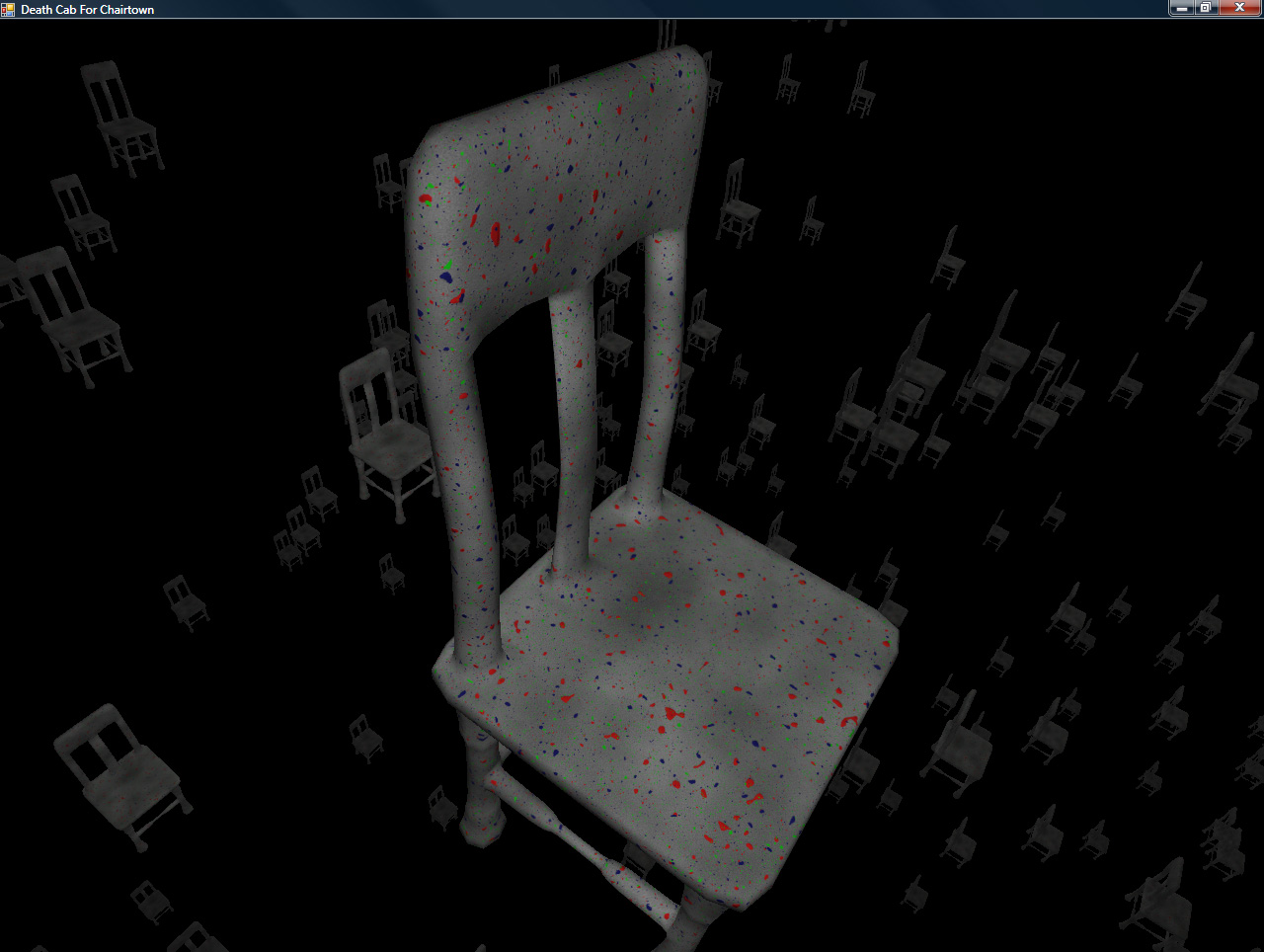
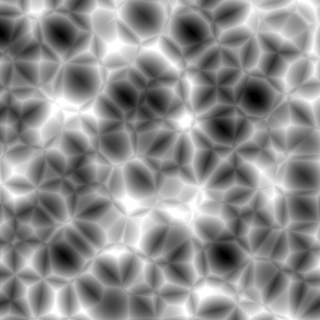
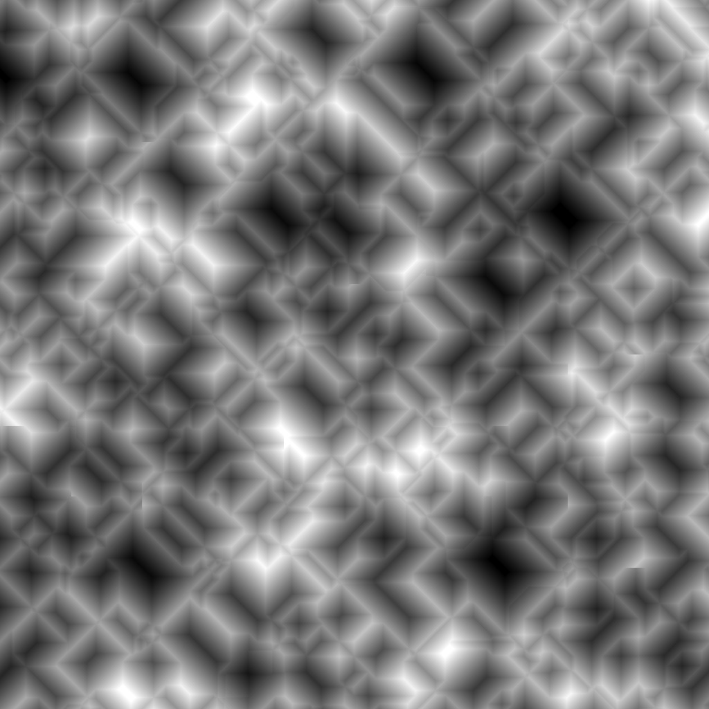
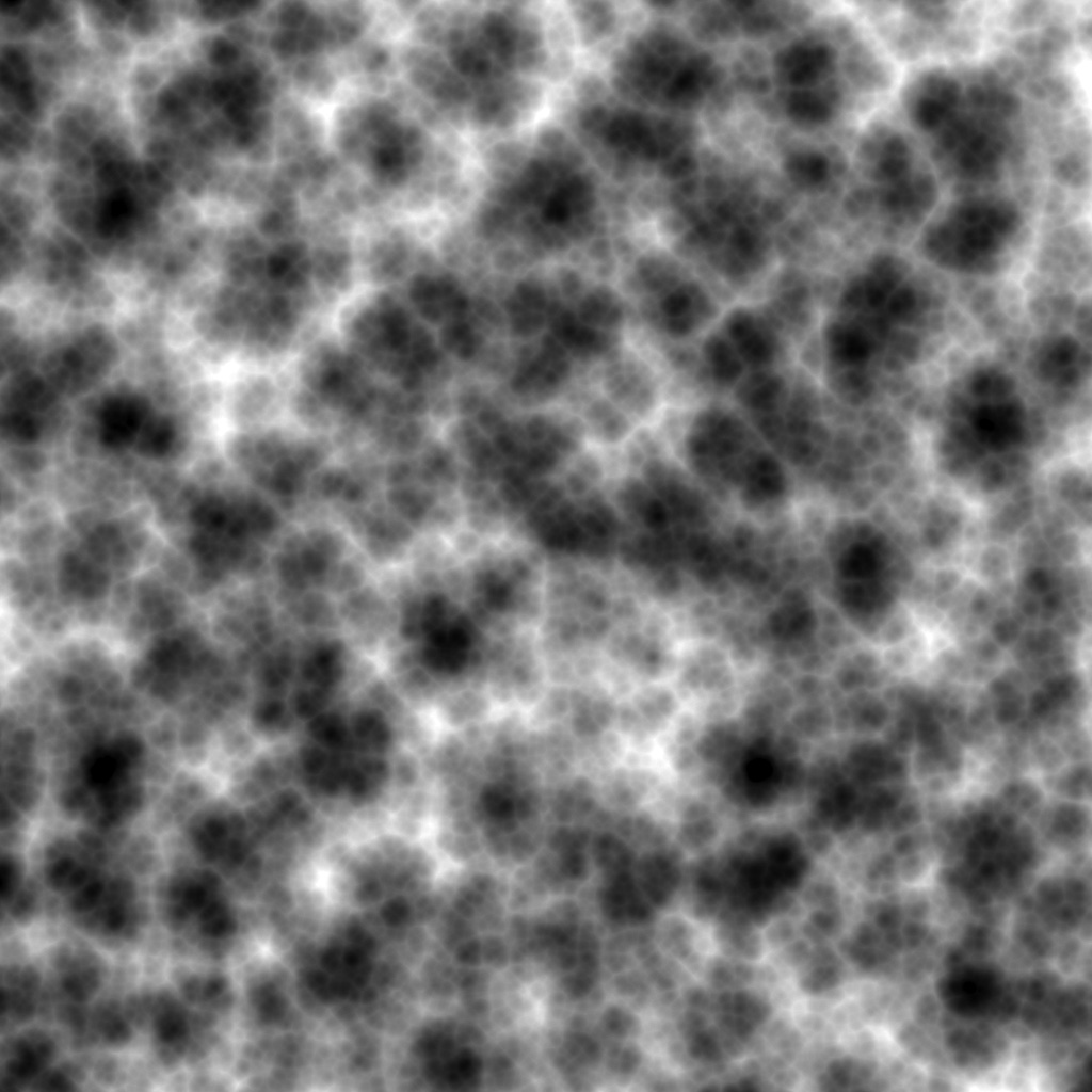
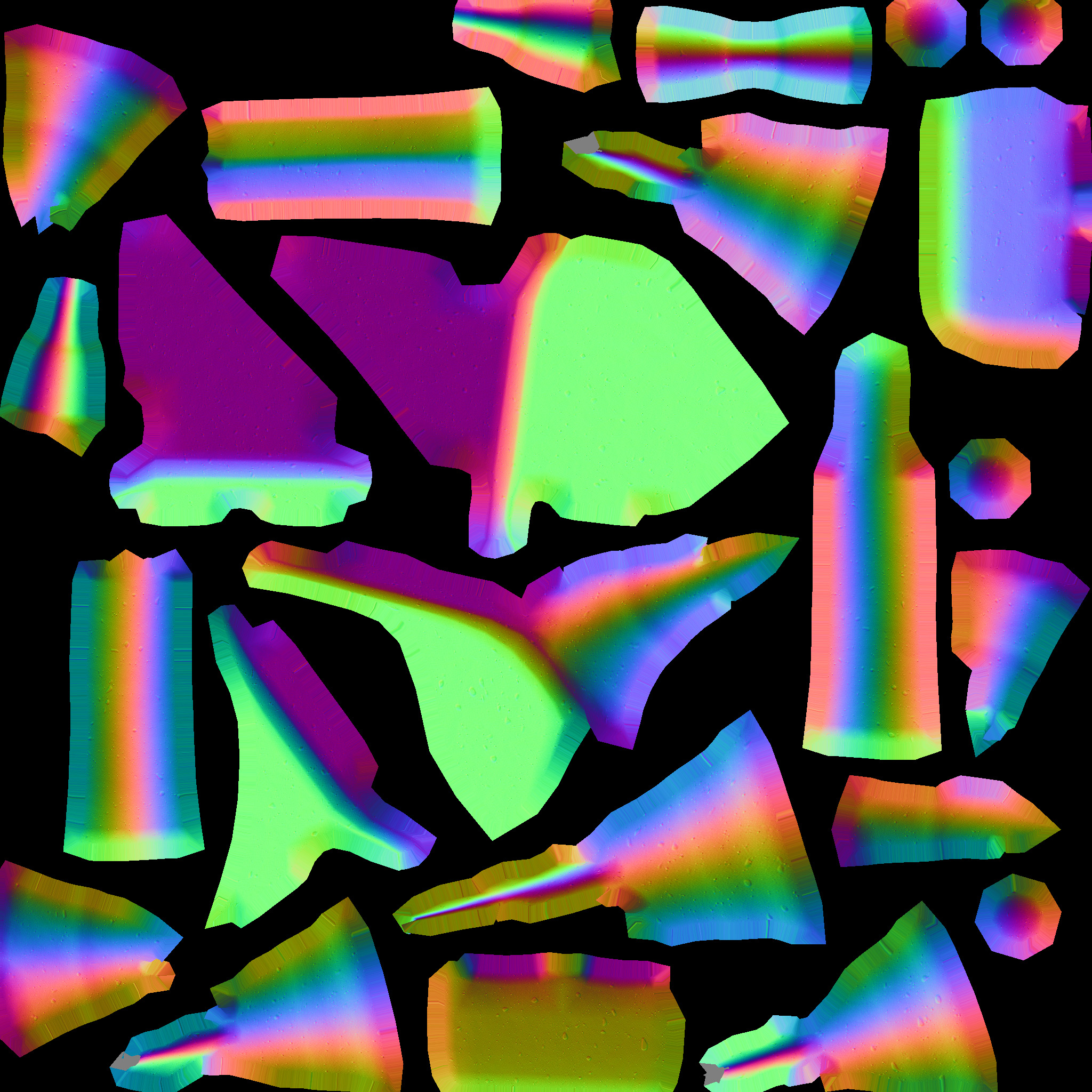
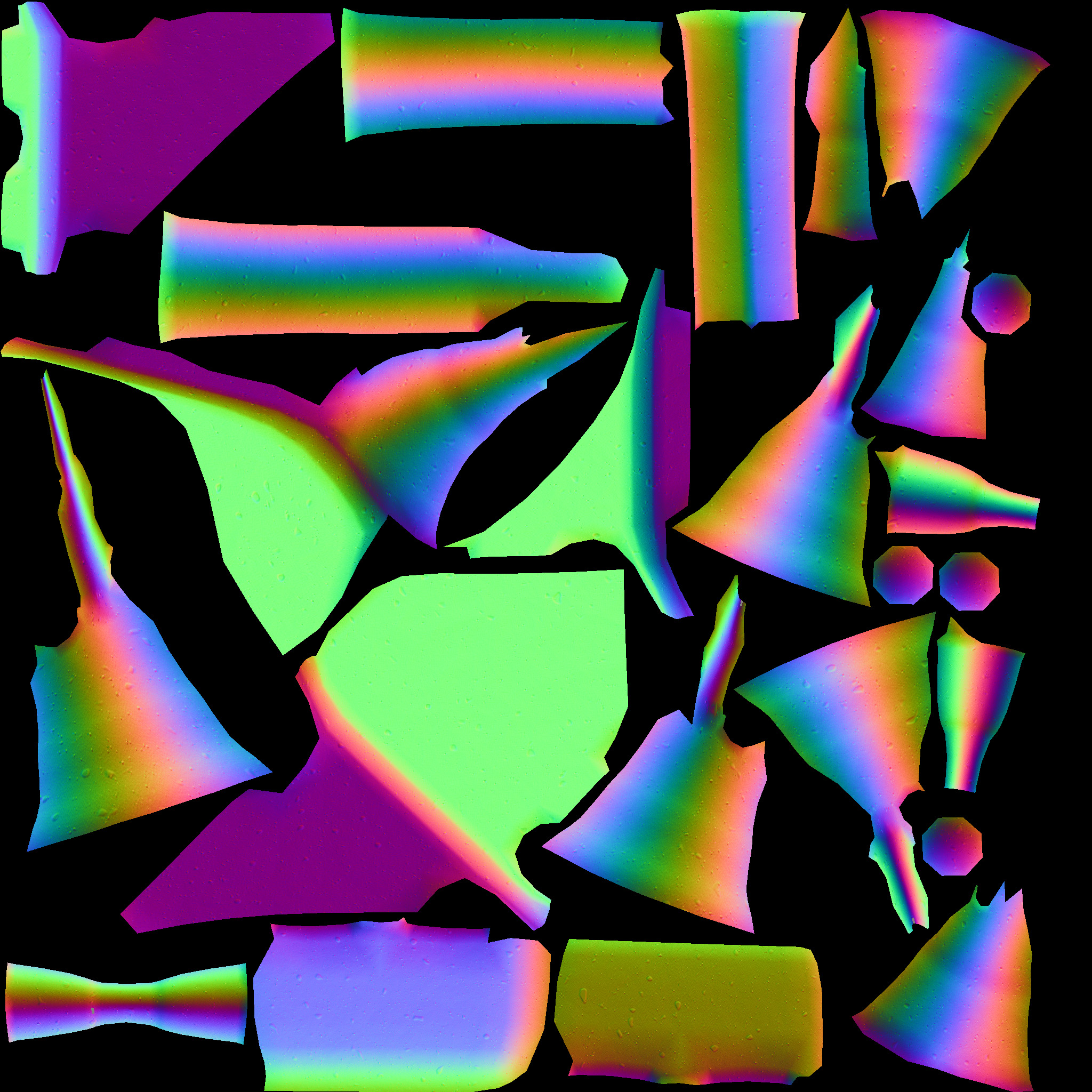
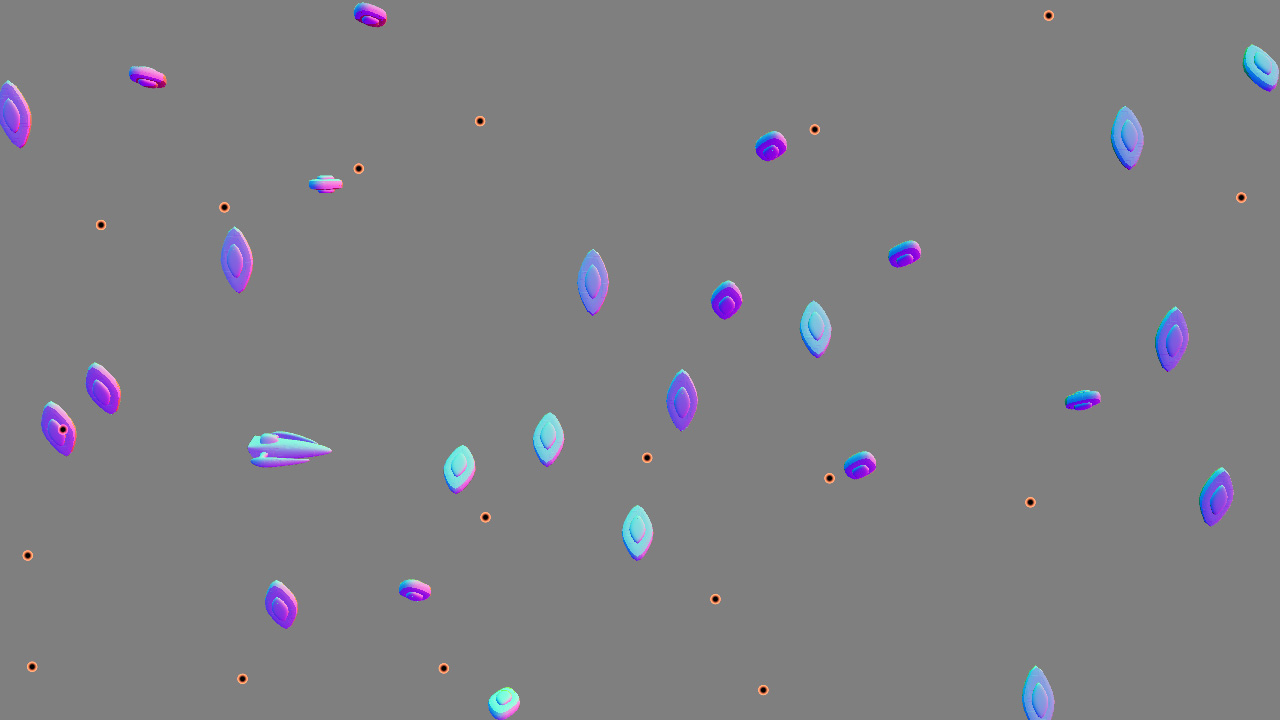
And, it generates the following data:


Click to enlarge

That’s the normal/depth texture (alpha not visualized) for the scene. The normals are in world-space (converting from the stored non-linear Z to world position using the texcoords is basically a multiply by the inverse of the viewProjection matrix, a very simple operation).

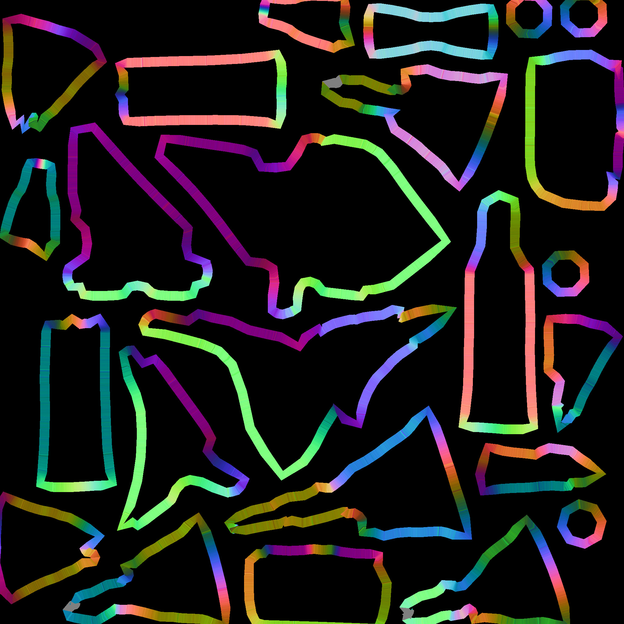
Render Pure Lighting (Put your junk in that box)

Next step, using that texture (the object normals and positions), you can render the lights as a screen-space pass very inexpensively (the cost of a light no longer has anything to do with the number of objects it’s shining on, it’s now simply a function of number of pixels it draws on). Bonus points: you can use a variation on instancing to render a bunch of lights of a similar type (i.e. a group of point lights) in a single pass, decreasing the cost-per-light even further.

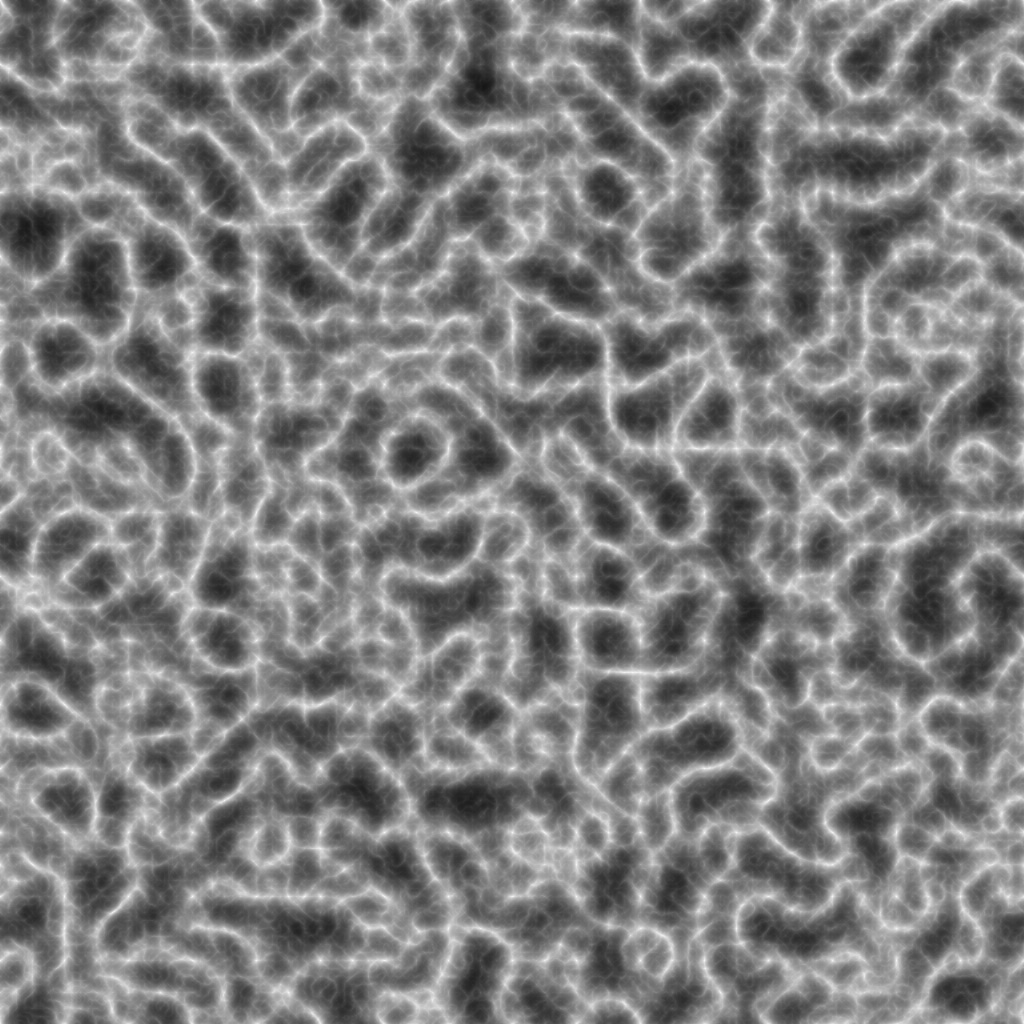
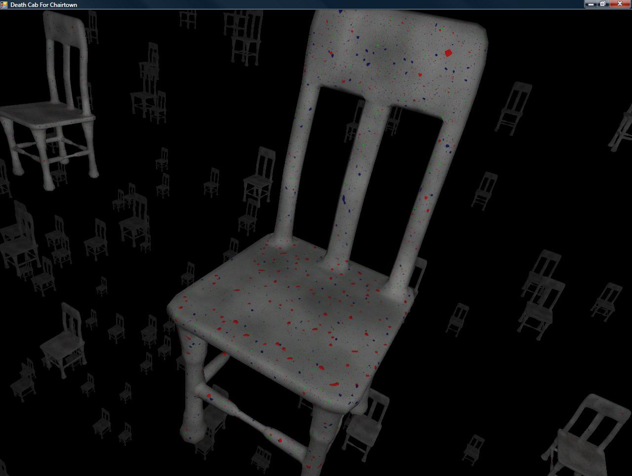
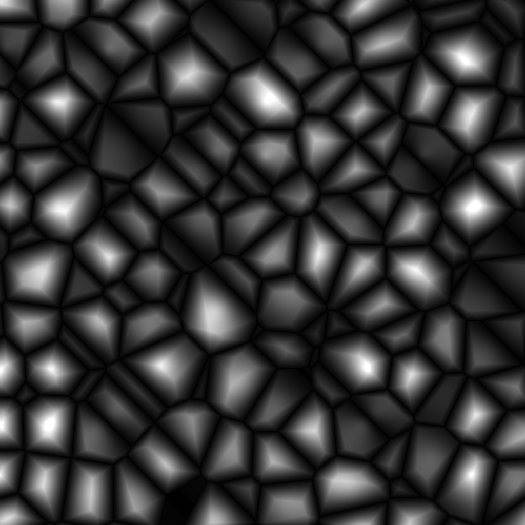
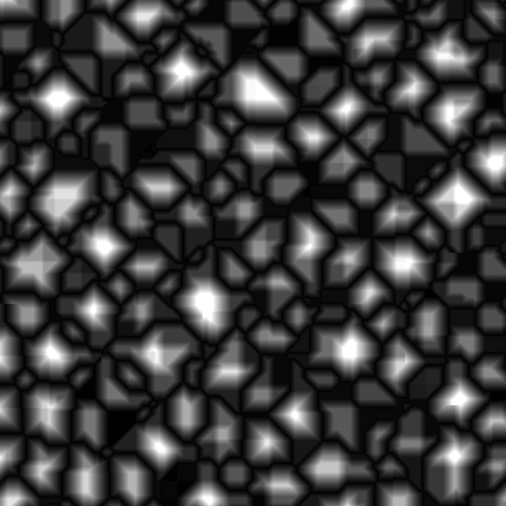
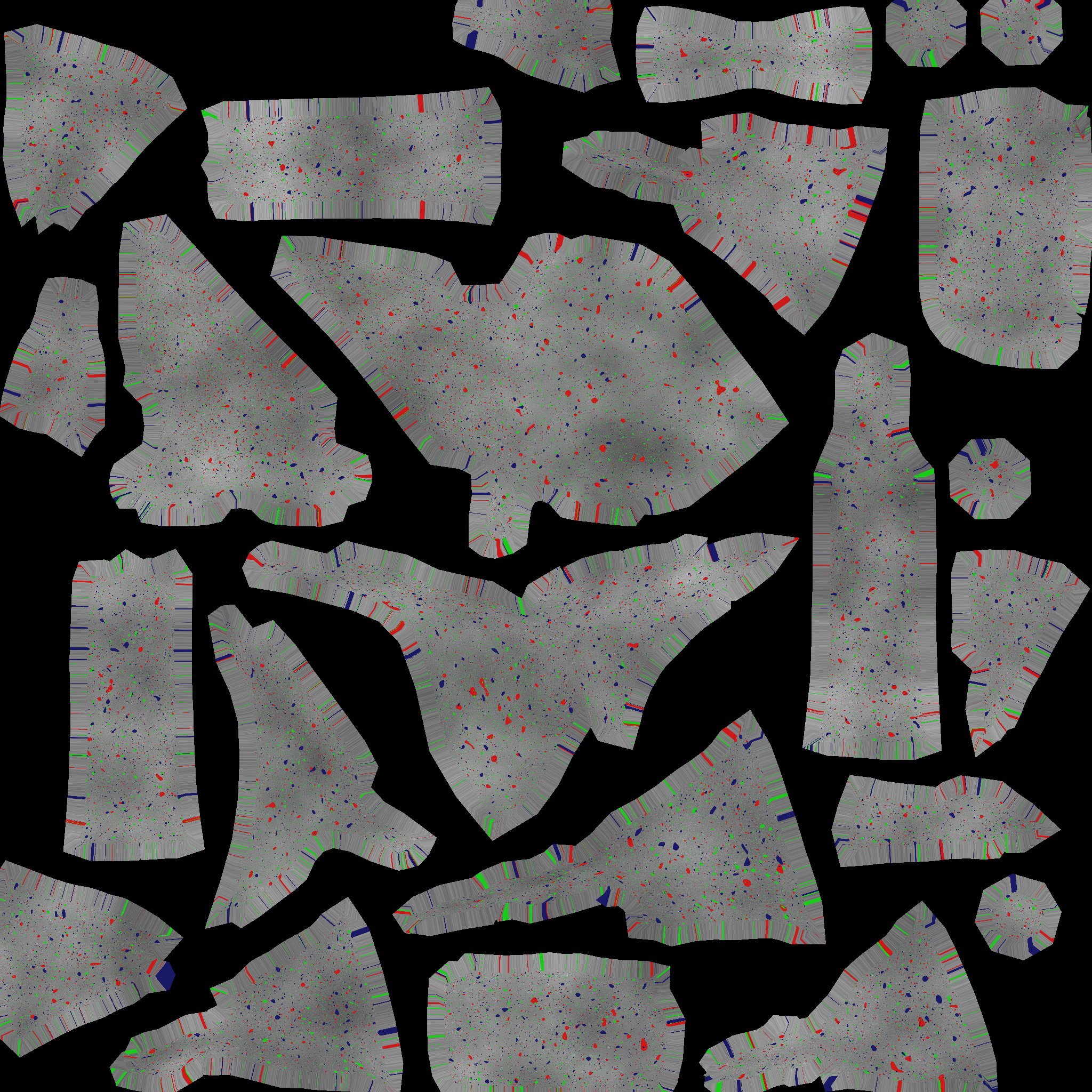
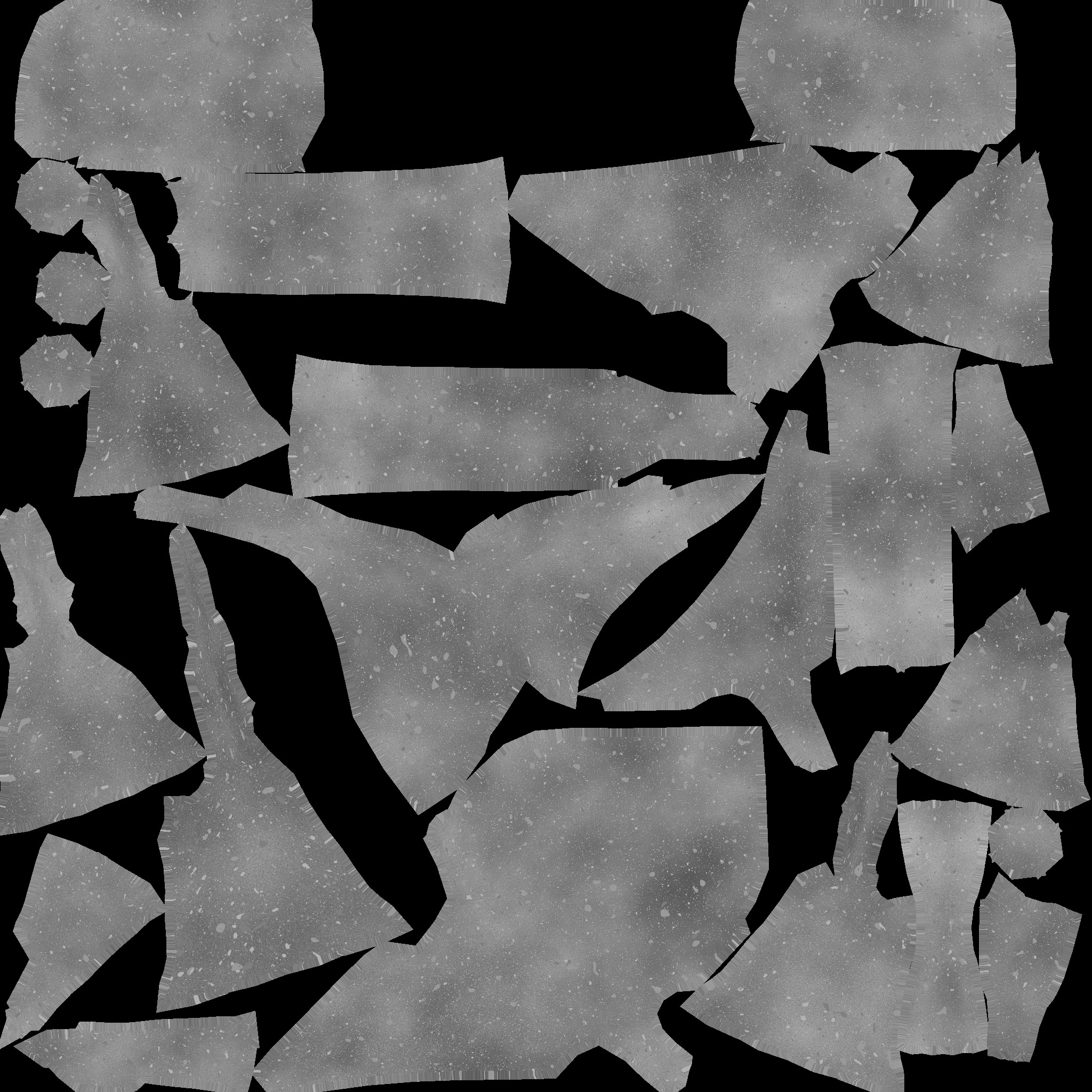
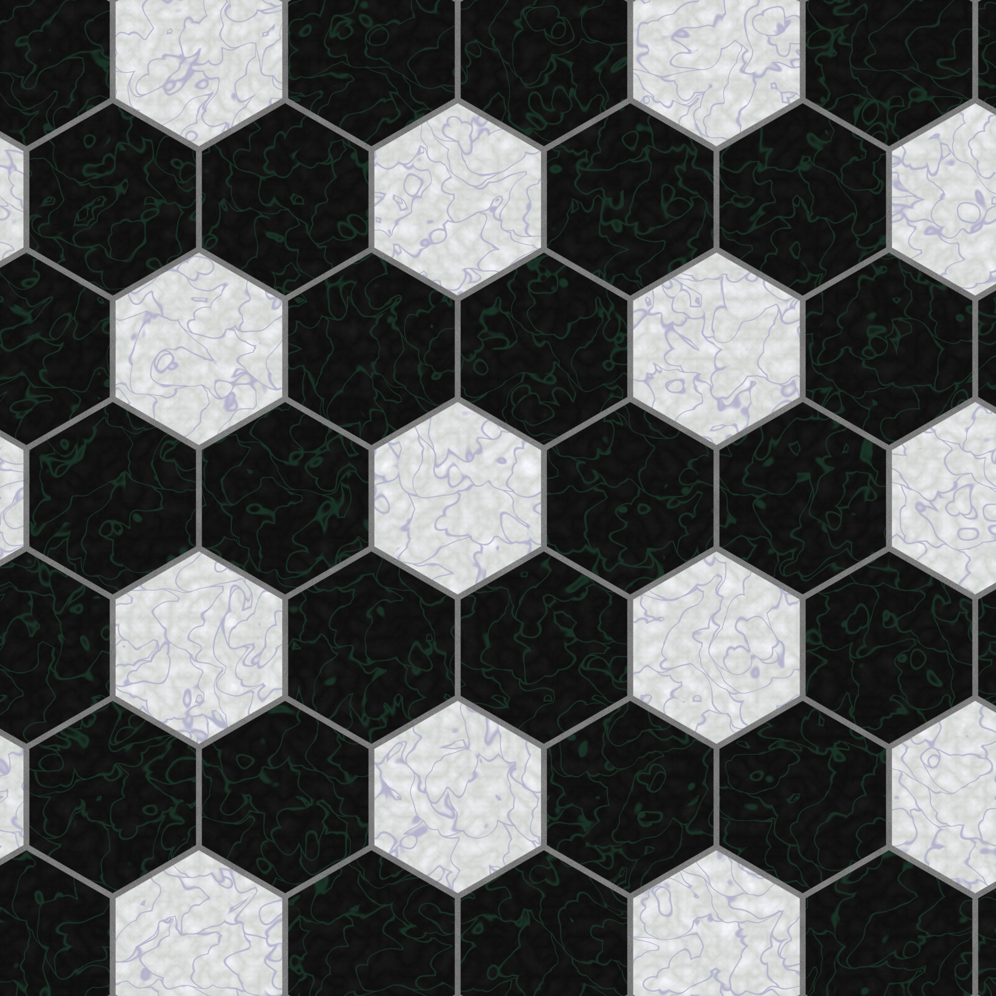
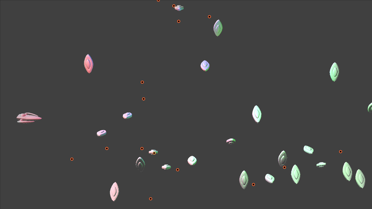
The lighting data (pure diffuse lighting, in my case, though this operation can be modified in a number of ways to do more material lighting types and/or specular lighting if necessary, especially if you have a separate depth texture) is rendered into another texture, and it ends up looking as follows:


Click to enlarge

That’s a render with three small point lights (red, green and blue in different areas of the screen) as well as a white directional light.

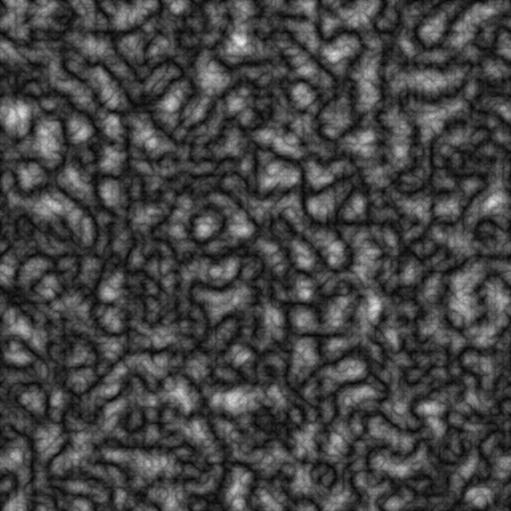
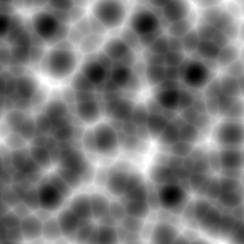
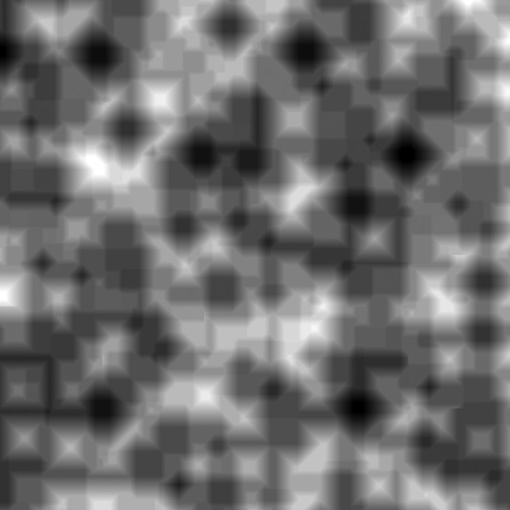
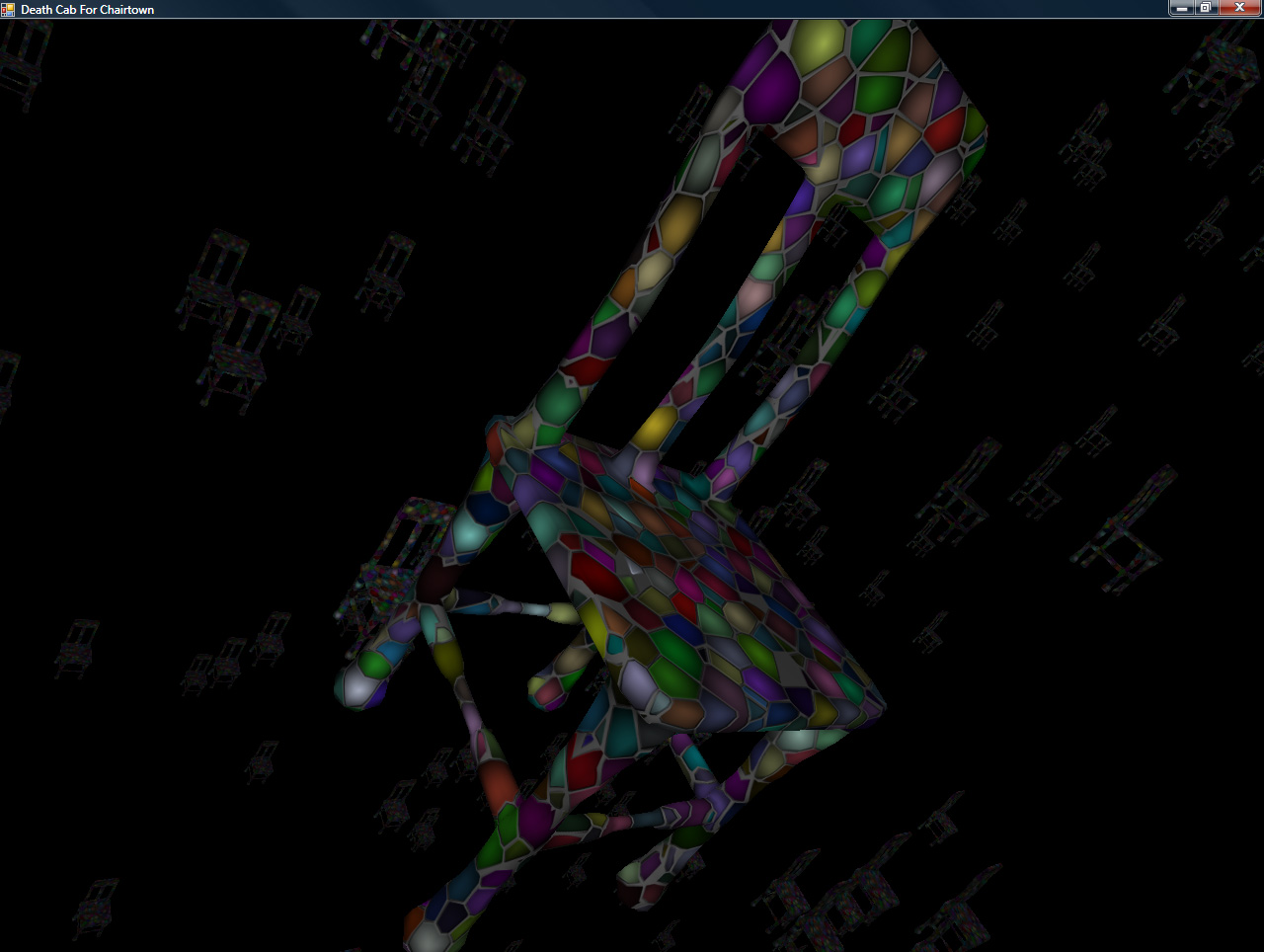
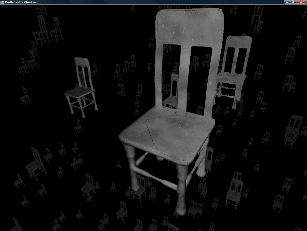
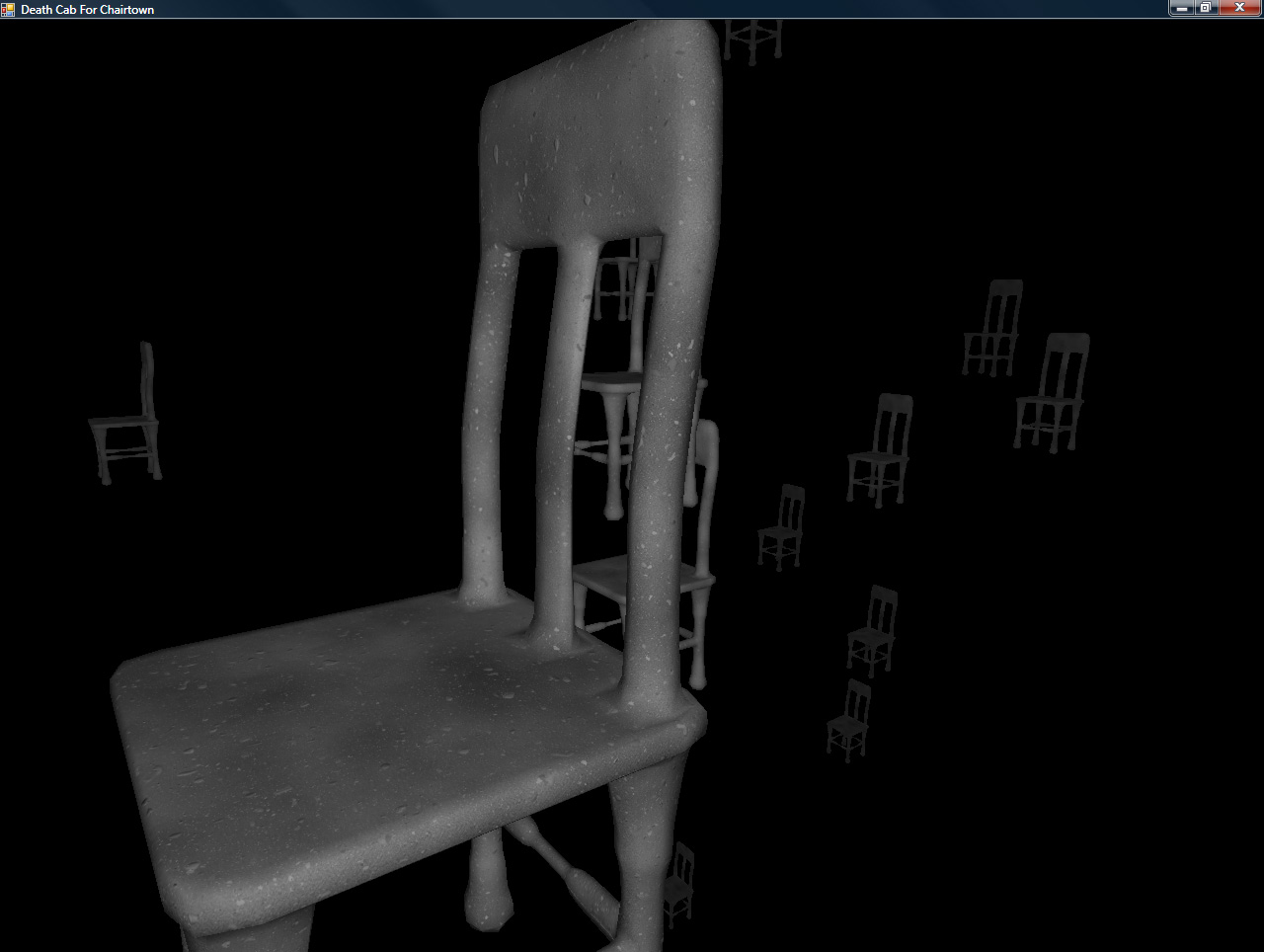
Render Objects With Materials (Make her open the box)

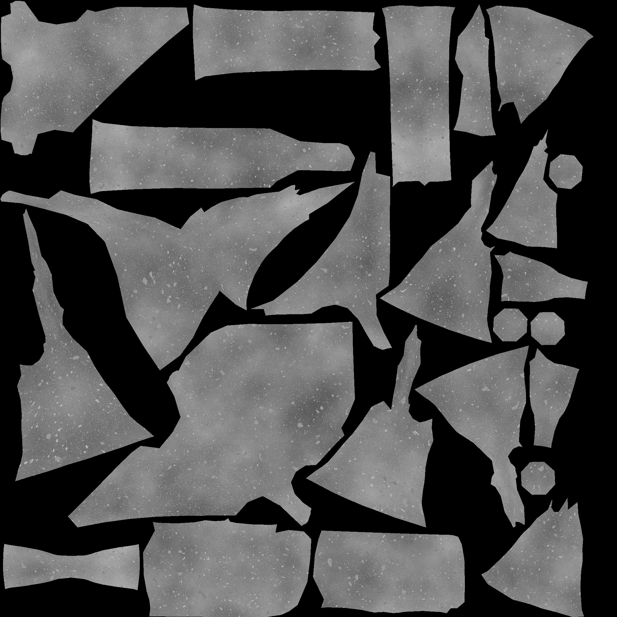
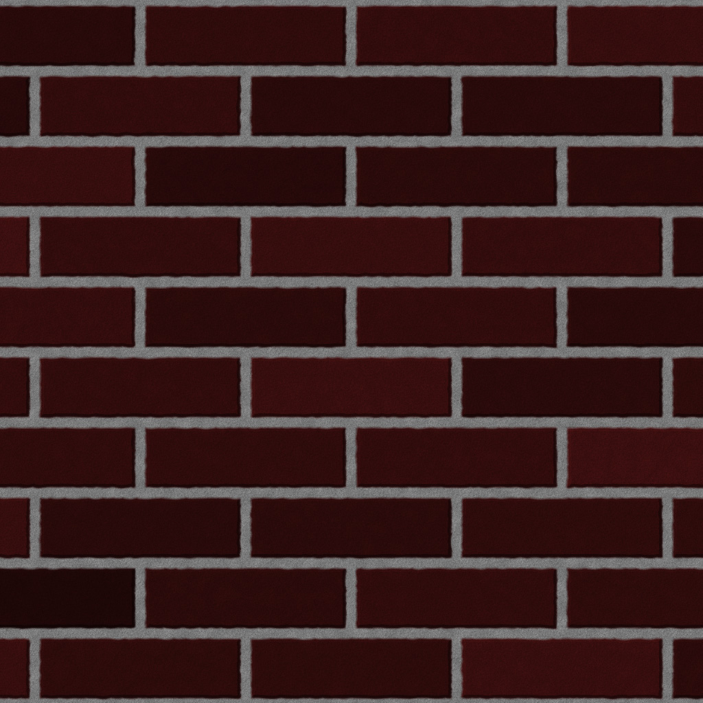
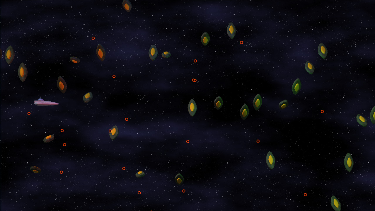
Finally, you render the objects again, only this time you render them with materials (diffuse texture, etc). However, instead of doing any lighting calculations at this time, you load them from the texture rendered in step 2.

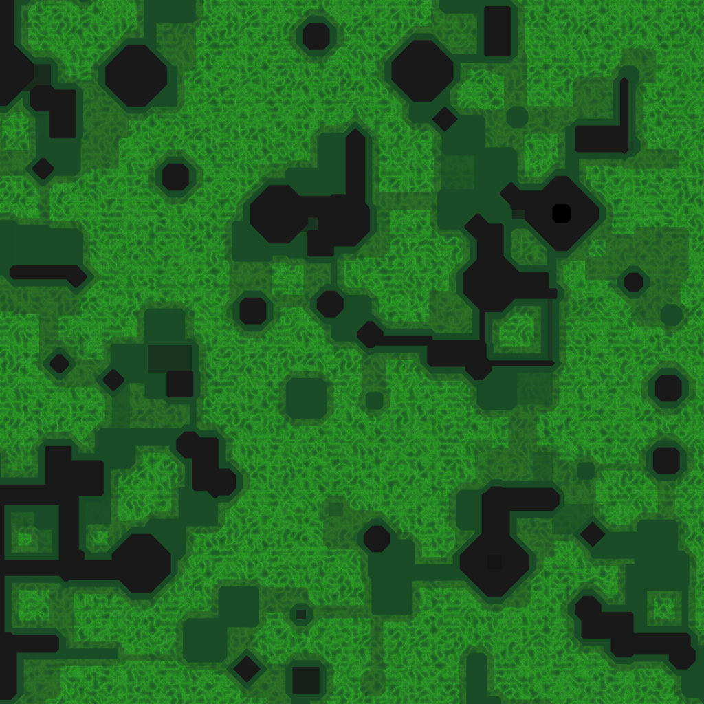
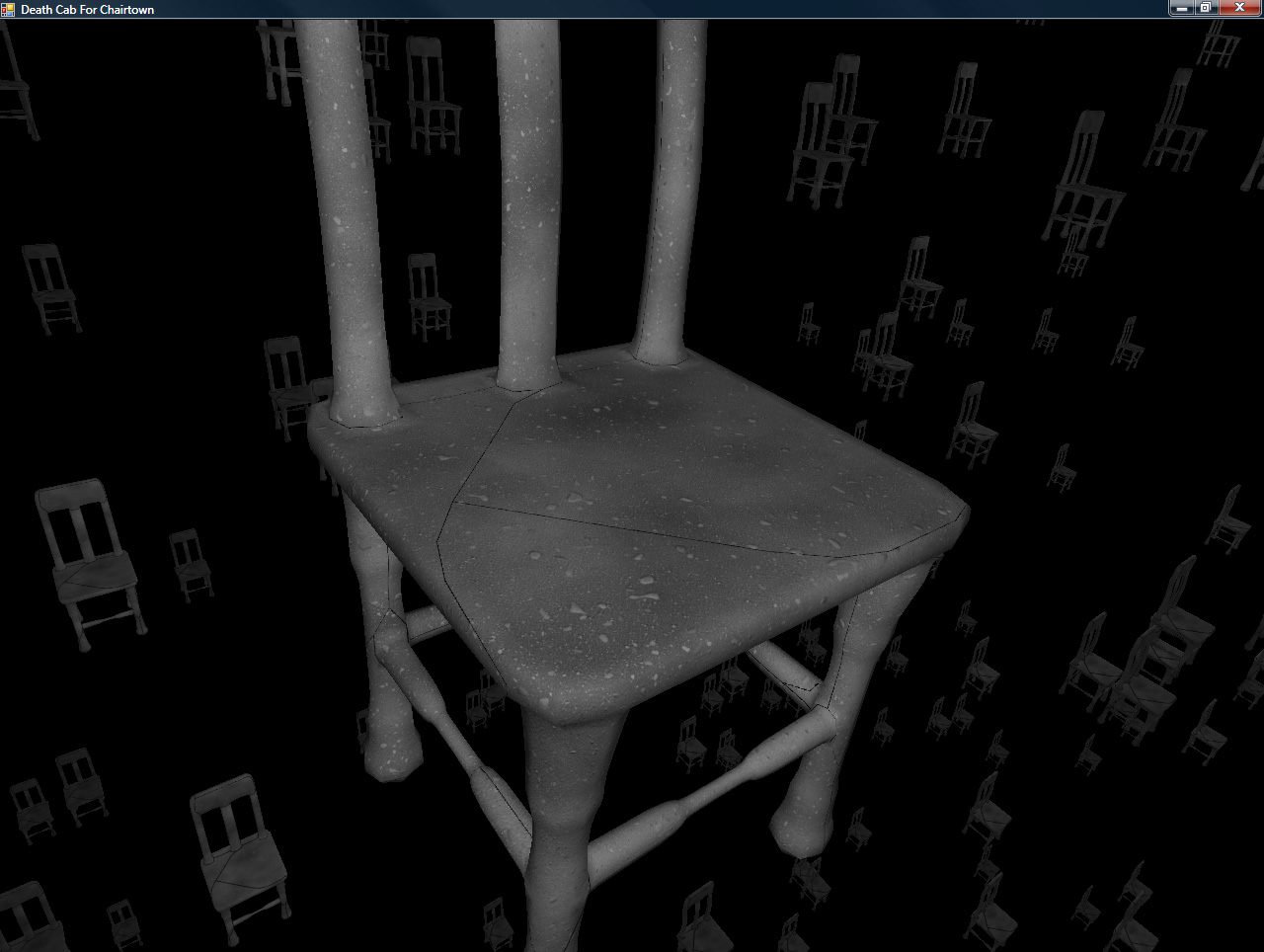
This ends up looking like this (pretty much what you expect from a final render):


Click to enlarge

And that’s how light pre-pass rendering works, in a nutshell. At least, it’s how it works in my case, which is very simplistic, but it’s all I need for the art style in my game. It’s a lot easier on the resources than deferred shading, while still separating the lighting from the objects.

Delicious!

Hopefully, in my next update, I’ll have an actual set of background objects (as that’s the next item on the list, but it does require the dreadful tooth-pulling that is “artwork,” so we’ll see how quickly I can pull this together.

Until next time: Never give up, never surrender!

Progress: Like Regress, Only Forward!

It’s been tricky to make much progress these last couple weeks – having a (non-gaming) coding job and being able to come home and work gets tricky, so a large majority of my game coding time is weekend time. Also, couple some deadlines at work, and you’ve got a large case of “I don’t want to code when I hit home.”

However: I did make a good deal of progress these last few weeks.

If you look at the screenshot in my last entry, it should be plain exactly HOW MUCH. Suddenly, my little experiment looks considerably like a GAME.


Click to enlarge

Also! GAMEPLAY VIDEO!
High Quality Xvid, 32MB
Low Quality Xvid, 3.5MB

Particles Make Me Sneeze

The biggest hurdle for this section of the project was the general-purpose particle system. Even though I’ve done a bunch of crazy graphics-related stuff, a particle system has NEVER been on that list. But no longer!

For my particles, I wanted the following data:

  • Position (3D)
  • Rotation (around Z)
  • Image Index (which image in the particle map to use)
  • Scale (how big the particle is scaled, relative to the particle map’s specified world size)

The particle map mentioned in that list is a simple list of texture coordinates into the particle texture (Which contains images for all of the particles), as well as the size of a given particle in world space.

The particles in this system are actually rendered using shader constants (2 float4 shader constants per particle), which gave me right around 100 particles per draw call. On my PC, I can push the system up to 24,000 particles before it starts to slow down. On the Xbox 360, it’s closer to 6000. Both of those are well within my game’s target maximum of 2000 particles, and I could probably get that number higher if I had to.

The State Machine Tells Way Fewer Lies Than the Political Machine

One thing I learned when working on Mop of Destiny was how to set up a totally sweet state machine in C++. I got to port those concepts over to C#, which made it even EASIER, given all of the reflection support. Note that I do the majority of the reflection calls at application startup, so the expensive calls are already done when it’s time to do the actual game running.

Each state can have three functions associated with it: Begin, Tick, End.

Begin is called on the transition to that state from some other state.
Tick is called every time the state gets run (once per frame)
End is called on the transition from that state to some other state.

Also, each state can have a number of transitions associated. They take the form of: “BooleanFunction = TargetState”

Every frame, before calling tick, the state machine core will run each of the specified functions. When one of them evaluates to true, it switches states to the new TargetState, which will then be run (unless one of ITS transitions triggers). A state can also call the SetState function direction, but having the transitions in the function attribute makes it really easy to see where a state can transition to.

See You Later, Allocater!

One of the most important things that I have been doing with my code is ensuring that, during the run of a game level, no memory is allocated. At all. The reason is the .Net garbage collector (GC).

The GC, on Windows, is triggered every 2MB of allocations (among other scenarios, including low-memory and lost-focus cases). On the Xbox 360, the GC runs ever 1MB of allocations. Since the GC pauses all threads while it does its thing, it’s better that it’s never triggered during runtime…ESPECIALLY if the heap is complicated and garbage collection is going to take a while.

To handle this, I’ve created a few of my own data structures, including the OrderlessList<T>. I’ve used OrderlessLists alot throughout my code. Simply stated, it’s an array (allocated at the time of the object with some maximum number of elements) in which the order of the objects is unimportant (i.e. it can be reordered and it doesn’t matter). Given the property of being able to reorder at any time, removal from the list is a simple matter of copying the last list over the top of the element being removed, then decreasing the reported size of the list.

For the bullets (both the player and the enemy bullets), there’s an OrderlessList of live bullets, and an OrderlessList of dead bullets. Whenever a bullet is needed, an object is retrieved from the dead bullet list, given its properties, and added to the live bullet list. Whenever a bullet dies (goes off-screen or hits an enemy), it is deactivated and returned from the live bullet list to the dead bullet list. No allocations necessary.

That’s right, it’s the ol’ “pool of objects so you don’t have to allocate” trick. But hey, it works!

Rambling Is For Cowboys, Not Coders

Alright, enough talk! Tomorrow is another day at work, so it’s likely I won’t make any more progress until next weekend.

In the meantime, death is but a door, time is but a window; I’ll be back.

Mork Calling Drilian, Come in, Drilian

I haven’t had nearly as much time to get stuff done at home as I’d like, as work has been a bit of a scramble recently. Working ridiculously hard at a code-related day job and then coming home and trying to code is…difficult. And recently, highly unsuccessful.

However, this last weekend I was able to get a few things done.

Silos Are Not Just For Grain and Missiles

First up, I decided to check out Nevercenter Silo, a 3D modeling program that I swear has to be the easiest-to-use modeling software I have ever SEEN. For some reason, this software just completely clicks with me.

Maybe it’s that it allows me to start with something as simple as a box and push/pull/extrude/warp/etc it slowly into the shape that I want, or maybe it’s that it has built-in support for symmetrical modeling (you basically model HALF of a model and the other half changes shape along with it). It’s hard to say. However, it feels more like sitting down with clay and slowly morphing it into the shape that I want vs. the usually-cumbersome task of modeling a 3D mesh.

Consequently, not terribly long after I got it, I modeled what will likely be the first ship for my new game!


Click to enlarge

I used subdivision surfaces to do the modeling, so the source geometry (pictured to the left above) is actually rather simple. But when subdivided, it forms (what I think is) a pretty cool-looking spacecraft.

S.S. Procedural Is Leaving Port

I also managed to get my procedural content (textures, mostly) generation ported over to run on XNA (from C++, so it was a bit of work). Since I’m aiming to release this game as part of the XNA dealy on the 360 (with an option for XBLA if I’m really, really lucky), I’ve been taking great care in ensuring that it is going to run well on the Xbox 360. So far, so good. I have background asset generation working, etc etc.

But more importantly, I have my ship model loading into the game.

AND it’s procedurally textured using my super-spiffo texture generation framework, so that’s awesome, too.

Check it: (Yes, that is a wireframe bezier patch in the background and yes, that means I’m also going to have procedural geometry generation)


Click to enlarge

So, to sum: not a lot of coding done (the overwhelming majority of that has been done at work), but I do finally have some pretty new screenshots!

Slow Progress Is Still Progress

I’ve gotten less done recently that I would have liked, due to a lack of time to sit down at my computer. However, I did implement tiling perlin noise in-shader.

It uses the same basic technique as I used to set up the tiling noise (so you can read it in one of my earlier posts).

Basically, I can generate perlin noise that tiles at any given (integer) position.

Quite handy for generating tiling textures (because not everything I’m generating needs to be 3d)

Here are some examples. It’s hard to tell that they tile without actually tiling them yourself, but they do. So there.


Click to enlarge

So I used it to put together a seamless version of my earlier brick texture:


Click to enlarge

Finally, I did the same basic trick with the Worley (cellular) noise.

The first screenshot is a large area repeating Worley, the second repeats at a very small level so it should be obvious how it tiles, even looking at the thumbnail:


Click to enlarge

Next up: Maybe I should actually do something useful with these things.

Jpeg Buoys Amidst a Sea of Text

So I put off working on this entry long enough that it’s now two entries worth of data in one.

Too Many Instructions: Cutting Down On the Noise

So, the implementation of Improved Perlin noise from GPU Gems 2 boils down to 48 pixel shader instruction slots (9 texture, 39 arithmetic). That’s one octave of noise. What I needed, desperately, was a faster implementation of noise, where the base quality doesn’t matter (especially useful for things such as fBm and the like).

In the FIRST GPU Gems, in the chapter on Improved Perlin Noise, Ken Perlin makes a quick note about how to make a cheap approximation of perlin noise in the shader, using a volume texture. The technique is straight forward, but it took me some effort to understand exactly what was supposed to go into the volume texture.

In my case, I ended up using a 32x32x32 volume texture to simulate an 8x8x8 looping sample of perlin noise space. Essentially, when sampling this texture, divide the world position by 8, and use that as the (wrapped) texcoord into the volume.

Crazy 8s: Modifying Perlin Noise To Loop At A Specified Location

The first trick is that it has to be LOOPING Perlin noise. But how do you generate such a thing?

Turns out, in the reference implementation of Improved Noise, there are a bunch of instances where there are +1s. For instance:

A = p[X  ]+Y;
AA = p[A]+Z;
AB = p[A+1]+Z;

B = p[X+1]+Y;
BA = p[B]+Z;
BB = p[B+1]+Z;

(Later, AA, AB, BA, and BB are also accessed with +1s).

Figuring out how to make the noise wrap at a specific value (in my case, 8), was a matter of rethinking those as follows:

A = p[X  ]; // note: no +Y here
AA = p[A+Y]  (+Z); // +Z in parens because it actually gets added later, like the Y does here
AB = p[A+(Y+1)] (+Z);

B = p[X+1]; // again, no +Y
BA = p[B+Y] (+Z);
BB = p[B+(Y+1)] (+Z);

So, really, the +1s are added to the coordinate added earlier.
So, to make the noise wrap at a certain value, you need to take those (coordinate+1)s and change each into a ((coordinate+1)%repeatLocation).

The final version of the texture shader that generates noise that loops at a specific location is as follows:

// permutation table
static int permutation[] = { 151,160,137,91,90,15,
131,13,201,95,96,53,194,233,7,225,140,36,103,30,69,142,8,99,37,240,21,10,23,
190, 6,148,247,120,234,75,0,26,197,62,94,252,219,203,117,35,11,32,57,177,33,
88,237,149,56,87,174,20,125,136,171,168, 68,175,74,165,71,134,139,48,27,166,
77,146,158,231,83,111,229,122,60,211,133,230,220,105,92,41,55,46,245,40,244,
102,143,54, 65,25,63,161, 1,216,80,73,209,76,132,187,208, 89,18,169,200,196,
135,130,116,188,159,86,164,100,109,198,173,186, 3,64,52,217,226,250,124,123,
5,202,38,147,118,126,255,82,85,212,207,206,59,227,47,16,58,17,182,189,28,42,
223,183,170,213,119,248,152, 2,44,154,163, 70,221,153,101,155,167, 43,172,9,
129,22,39,253, 19,98,108,110,79,113,224,232,178,185, 112,104,218,246,97,228,
251,34,242,193,238,210,144,12,191,179,162,241, 81,51,145,235,249,14,239,107,
49,192,214, 31,181,199,106,157,184, 84,204,176,115,121,50,45,127, 4,150,254,
138,236,205,93,222,114,67,29,24,72,243,141,128,195,78,66,215,61,156,180
};

// gradients for 3d noise
static float3 g[] = {
    1,1,0,
    -1,1,0,
    1,-1,0,
    -1,-1,0,
    1,0,1,
    -1,0,1,
    1,0,-1,
    -1,0,-1,
    0,1,1,
    0,-1,1,
    0,1,-1,
    0,-1,-1,
    1,1,0,
    0,-1,1,
    -1,1,0,
    0,-1,-1,
};

int perm(int i)
{
	return permutation[i % 256];
}

float3 texfade(float3 t)
{
	return t * t * t * (t * (t * 6 - 15) + 10); // new curve
//	return t * t * (3 - 2 * t); // old curve
}

float texgrad(int hash, float3 p)
{
  return dot(g[hash%16], p);
}

float texgradperm(int x, float3 p)
{
	return texgrad(perm(x), p);
}

float texShaderNoise(float3 p, int repeat, int base = 0)
{
	int3 I = fmod(floor(p), repeat);
	int3 J = (I+1) % repeat.xxx;
	I += base;
	J += base;

  p -= floor(p);

  float3 f = texfade(p);

	int A  = perm(I.x);
	int AA = perm(A+I.y);
	int AB = perm(A+J.y);

 	int B  =  perm(J.x);
	int BA = perm(B+I.y);
	int BB = perm(B+J.y);

  	return lerp( lerp( lerp( texgradperm(AA+I.z, p + float3( 0,  0,  0) ),
                                 texgradperm(BA+I.z, p + float3(-1,  0,  0) ), f.x),
                           lerp( texgradperm(AB+I.z, p + float3( 0, -1,  0) ),
                                 texgradperm(BB+I.z, p + float3(-1, -1,  0) ), f.x), f.y),
                     lerp( lerp( texgradperm(AA+J.z, p + float3( 0,  0, -1) ),
                                 texgradperm(BA+J.z, p + float3(-1,  0, -1) ), f.x),
                           lerp( texgradperm(AB+J.z, p + float3( 0, -1, -1) ),
                                 texgradperm(BB+J.z, p + float3(-1, -1, -1) ), f.x), f.y), f.z);

}

Whee!

Noise + Real Numbers + Imaginary Numbers == ???

So, the second trick: the texture actually needed to contain two values (R and G channels), to act as real and imaginary parts. Very simple, I added a base parameter (in the code above) so that I could offset into a different 8x8x8 cube of noise. I drop a different 8x8x8 noise into the G channel.

Finally! We have a texture with 8x8x8 noise. But 8-cubed noise sucks, because it’s ridiculously repetative. That’s where that weird imaginary part comes into play. You sample the 8-cube volume again, but at 9x scale (so it’s lower frequency). You then use the (real component of) high-frequency as an angle (scaled by 2pi) to do a quaternion rotation on the low-frequency noise.

float noiseFast(float3 p)
{
  p /= 8; // because the volume texture is 8x8x8 noise, divide the position by 8 to keep this noise in parity with the true Perlin noise generator.
  float2 hi = tex3D(noise3dSampler, p).rg*2-1; // High frequency noise
  half   lo = tex3D(noise3dSampler, p/9).r*2-1; // Low frequency noise

  half  angle = lo*2.0*PI;
  float result = hi.r * cos(angle) + hi.g * sin(angle); // Use the low frequency as a quaternion rotation of the high-frequency's real and imaginary parts.
  return result; // done!
}

And that’s it! Compare the instruction counts of the real Perlin noise to this fast fake:

Old (high-quality):  approximately 48 instruction slots used (9 texture, 39 arithmetic)
New (lower-quality): approximately 20 instruction slots used (2 texture, 18 arithmetic)

Essentially, wherever I don’t need the full quality noise, I can halve my instruction count on noise generation. Score!

Here’s a comparison: on the left, the weird confetticrete chair with the original noise, and on the right is the new faster noise:


Old (left) vs. New (right)
Click to enlarge

They look roughly the same, there are some artifacts on the new one (the diamond-shaped red blob on the upper-right of the new chair due to the trilinear filtering), but it’s way faster.

Cellular Noise

Okay, I have some cool perlin noise stuff. But man cannot live on Perlin noise alone, so I decided to implement cellular noise, as well.

Turns out, there’s something called Worley noise which does exactly what I was hoping to do. Implementation was pretty simple.

void voronoi(float3 position, out float f1, out float3 pos1, out float f2, out float3 pos2, float jitter=.9, bool manhattanDistance = false )
{
  float3 thiscell = floor(position)+.5;
  f1 = f2 = 1000;
  float i, j, k;

  float3 c;
  for(i = -1; i <= 1; i += 1)
  {
    for(j = -1; j <= 1; j += 1)
    {
      for(k = -1; k <= 1; k += 1)
      {
        float3 testcell = thiscell  + float3(i,j,k);
        float3 randomUVW = testcell * float3(0.037, 0.119, .093);
        float3 cellnoise = perm(perm2d(randomUVW.xy)+randomUVW.z);
        float3 pos = testcell + jitter*(cellnoise-.5);
        float3 offset = pos - position;
        float dist;
        if(manhattanDistance)
          dist = abs(offset.x)+abs(offset.y) + abs(offset.z);
        else
          dist = dot(offset, offset);
        if(dist < f1)
        {
          f2 = f1;
          pos2 = pos1;
          f1 = dist;
          pos1 = pos;
        }
        else if(dist < f2)
        {
          f2 = dist;
          pos2 = pos;
        }
      }
    }
  }
  if(!manhattanDistance)
  {
    f1 = sqrt(f1);
    f2 = sqrt(f2);
  }
}

The gist is that each unit cube cell has a randomly-placed point in it. for each point being evaluated by the shader, you find the distance to the nearest point (a value called “F1”), and the distance to the next-nearest (“F2”), etc (to as many as you care about – though anything past F4 starts to look similar and uninteresting). Using linear combinations of these distances gives interesting results:


Left: F1 Right: F2
Click to enlarge


Left: F2-F1 Right: (F1+F2)/2
Click to enlarge

Something cool to do, also, is to use Manhattan distance instead of standard Euclidian distance to calculate the distance. You end up with much more angular results. Here are the same 4 calculations, using manhattan distance:


Click to enlarge

Considering that a few levels of my current project will take place in a metallic fortress, this will especially come in handy.

So, what can you do with these?

I, predictably, have made a few test textures:


Click to enlarge

Also, it still looks pretty cool if you use fBm on it. For instance:


4 octaves of F1 Worley noise

But I hear you asking “duz it wrok n 3deez, Drilian?!?!?!” Oh, I assure you it does!


Click to enlarge

And now I hear you asking “Can u stop typing nau? I is tir0d of reedin.” (or alternately, “I is tir0d uv looking @ imagez sparsely scattered thru the text taht I dun feel liek reedin.”) To this, I say: Sure, but it worries me that you’re asking your questions in some form of lolcat.

That’s all I got.

Short Skirt, Long Jacket

So yesterday I got the crack filling up and running.

Tonight, I improved the routine dramatically.

The Trouble With Texcoords

The problem was, the edge-expanding algorithm I used was detecting way more edges than it needed to. Here’s an image of a normal map generated using this (old, bad) method (I made it render ONLY the skirts, for illustration):


Click to enlarge

As you can see, way more edges through the UV charts were getting expanded than necessary. This was messing up the maps, because there were angles and edges where there didn’t need to be, and it was introducing artifacts, especially at lower mip levels.

The problem arose because each of those “extra” edges marked areas where the vertex positions were the same, but the texcoords were different. Since the original algorithm was using the vertex’s index as the identifying feature, each time there was a texcoord change meant that the indices for neighboring triangles were different, blah blah blah, you get the point.

UV: Vectors, Not Rays

Basically, the system was rewritten to glom together vertices with the same uv map coordinates, and treat them as one single vertex. All of those interior edges get discarded. Because a single “vertex” could actually be composed of multiple source vertices, the edge expanding code had to be modified to take that into account.

Here’s the old way again, followed by the NEW way (And then the new way completely filled in):


Click to enlarge

As you can see, they’re now proper outlines (not outandsometimesinlines), and the actual outer areas are much cleaner.

I Don’t Think That Clown Is Healthy

So, here’s a new render (and its diffuse map). I modified the concrete because I was sick of all of my pictures being grayscale, so here’s my artist’s rendition of “Gray Chair That A Clown Puked Onto”:


Click to enlarge

That’s all! I’m going to release the code that I’m using for all of this, but I want to clean it up just a bit, and add variable gutter width support (instead of the lame hardcoded way that I have it now).

But for now…away!

The Big Procedural Easy

I took it easy today, so I was barely near the computer, but I did make some awesome progress.

Last night, I was able to finally get a prototype of my texture caching setup going.

Diffusing the Procedural Situation Using Bad Puns

Right now, it’s a command-line tool that does the following:

  • Loads up a mesh and UV atlases it to get unique texture coordinates for the entire mesh (similar to what you’d do for lightmapping
  • Loads a D3DX effect
  • Renders the mesh into the a render target, using the UV atlas texcoords as position, using the actual model’s position/normal as shader inputs to generate the noise
  • Writes both the UV atlased mesh and the rendered texture to file

Simple enough. What I ended up with was as follows:


Click to enlarge

Not bad, but for two things:

  1. No normal mapping (per-vertex normals only)
  2. Cracks along the seams of the UV maps.

Both are solvable problems, and I opted to tackle the normal mapping first.

Returning to Normalcy

How does one generate a normal map with a procedural function?

In my case, I have the procedural function not only generate a color but a height. Generating three heights in close proximity (using (pos), (pos+tangent*scaler), (pos+bitangent*scaler)) gives me two edges which I can take the cross-product of to get a pixel normal map. Adding this gave me some better shading (but didn’t fix the cracks):


Click to enlarge

The normal map generated is in object space (though it could easily be in world space, assuming a static object). This simplifies the lighting code (I simply transform the light position by the inverse world matrix before passing it to the shader) and eliminates the need for tangent and bitangent (yes, bitangent, not “binormal”) vectors.

Cracks are Unappealing on Plumbers AND Procedurally-Textured Models

Finally, it was time to solve the cracking problem. I decided to solve it by using skirts around the edges of the UV map sections. Essentially, they’re degenerate textures in the actual mesh (the positions are the same), but the UV coordinates are expanded to fill in some of the gapping.

Basically:

  • Use your favorite method to get a list of edges that are only used once
  • Use these edges to generate “UV normals” for each vertex (which has two edges, one leading in and one leading out), which are basically ( perpendicular[(edge+edge2)/2] ).
  • duplicate each vertex, move its UV coordinate some distance along this uv normal
  • Create new strips of indices, using the old and new
  • render these into the UV map first, before rendering the standard data

This basically puffs out each procedurally-generated area, as you can (maybe) see here (Easier to see at full size):


Click to enlarge

Thus, when the UV coordinates along the edges of these areas either go out of bounds or blend with the no-man’s-land around the texture, it blends with data that’s very close to what it’s near, hiding the cracks.

The result:


Click to enlarge

And that’s “all” there is to it!

The UV atlasifying and skirt generation will be a pre-process, so all of the vertex (mesh) data will be ready for immediate rendering into the texture after load.

Woot!

Sometimes They Come Back

Return of the chairs!

I needed a quick test to make sure that the noise textures work well in 3D, since that’s their intended use, so I decided to run them on some chairs.

A few things to note:

  • These aren’t currently being written to texture first (which is the ultimate idea) so the chairs in the background have a certain amount of…sparkle.
  • Also, this means that this is SLOW. This scene brought my 8800GTX to its little silicon knees. The concrete shader is 1906 instructions (way over the sm3 guaranteed min spec of 512), 306 texture and 1600 arithmetic, so it’s a bit…intense.
  • The lighting looks a little weird. I’m not sure if it’s an artifact or if it’s right and I’m just imagining things, but there you go.


Click to enlarge

That’s all!

PS – broken finger: still sucks.

More Textures!

This’ll be a short update. I came up with a better pavement texture, and, while trying for the stones, came up with a nice method of star generation, so I refined that as well. Hooray for happy accidents!

The stars one really looks best zoomed in (the thumbnail looks kinda lame), but I like them both!


Click to enlarge

All 100% pixel-shader generated. Both of these use pure improved perlin noise modifications to generate their look…no custom patterns like the brick and tile textures from earlier.

If you want to play around with the generator, the binary, code, and shaders are in a zip in the previous post. Have at it and let me know if you make anything awesome!

Procedual Terseness

The Most Communicative Of Fingers

This entry was going to be a bit longer, but:

OWW MY LMF ASPLODE!

Yeah. It’s the classic tale of “boy meets girl, girl rejects boy,” except you replace “boy” with “finger,” “girl” with “wall,” and “rejects” with “breaks.”

Sometimes playing wallyball can be considered dangerous.

Procedural Textures

As part of the framework for the game I am currently writing, I’m going to have as much texture data as possible be procedural and cached in on the fly. There are a few reasons for this choice (many of which should be obvious):

  • Less disk usage – very useful if I hit my target of, oh, say, a certain game console
  • Non-repeating textures – textures don’t have to tile. I can keep caching in new ones.
  • Seriously, I suck at texture art – This way, the computer does it for me!

I’m still working on the method, but here are a few examples:


Click to enlarge

These are all generated on-GPU, using ps_3_0 shaders. The noise implementation comes straight (thank you, copy-and-paste) from GPU Gems 2, which is an awesome book.

The idea is that objects (especially static world objects) will have unwrapped UV coordinates (like you’d use for lightmaps). To generate the textures onto the objects, I’ll do the following:

  1. Create a texture that is the requisite size (or pull it out of a pool, which is more likely
  2. Render the objects into the texture, using the UV coordinates as the position (scaled from [0,1] to [-1,1] of course).
  3. Pass the position and/or normal to the pixel shader, use it to generate the texture data
  4. Repeat for as many textures as the object needs (some combination of diffuse color, normal, height, glossiness, etc).

Should be pretty easy. Obviously, there are some patterns that are ridiculously difficult or even maybe impossible to generate efficiently on the GPU, so I’ll probably still use some pre-made texturemaps. But as much as I possibly can do on the GPU, I will. The main gotcha will be keeping the amount of texture info that needs to be generated to a minimum, so there aren’t any render stalls. That’s more of a level design/art problem though (which, because this is being developed lone-wolf, is also my problem).

If you want to see the shaders I’ve used and the code that I used, here is my sample app (with full source):

ProcTexGen.zip – 29KB.

The source is ridiculously uncommented because I coded it over the span of maybe 3 hours as a quick prototype, and the shaders are, I’m sure, nowhere near efficient. Also, they don’t handle negative values very well, which is why many of them add 100 to the coordinates (HACKHACKHACK).

Enjoy! And if you make any awesome textures with it, please let me know 🙂