Understanding Half-Pixel and Half-Texel Offsets

For those of you not using Direct3D 9 or XNA, you can safely ignore this post (OpenGL and Direct3D 10 are immune to this particular oddity).  However, if you are, it’s likely that you’ve had to deal with the dreaded half-texel offset.  Today, after I don’t know how many years of using Direct3D, I came to realize that I really didn’t understand what the source of the issue was.  Now that I’ve sort of gotten a handle on it, I figured I’d post it to my super new journal.  Consider it a test run.

Coordinate Spaces

The first thing to note is the basic coordinate space.  I’m going to be referring to texture space and clip space a lot, so I thought I’d just do a quick refresher here on what I mean (mostly to make sure you’re thinking with the same terminology that I’m using).

  • Clip space – the post-projection half-cube of space where X,Y in [-1..1] and Z in [0..1]
    • X = -1 is the far left edge of the screen
    • X =  1 is the far right edge
    • Y = -1 is the bottom edge
    • Y = 1 is the top
    • Z = 0 is near (the near plane)
    • Z = 1 is far (the far plane)
  • Texture space – the area where u,v in [0..1] on a texture map making up a single end-to-end repeat of the texture.
    • 0,0 represents the upper-left coordinate on the texture
    • 1,1 is the lower-right.

For simplification, we can ignore the Z direction in clip space, since this article is really about the screen-space aspects of it.

Texture Sampling

Texture sampling is pretty straightforward.

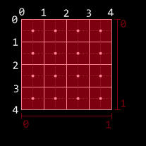
In this diagram (and future diagrams), I’m using a 4×4 texture.  The [0..1] range in both X and Y map exactly to the range of the texture.  Note, here, that the center of the upper-left texel does not lie at 0,0; instead, 0,0 refers to the upper-left corner of that texel.  This is an important thing: if you are using bilinear filtering and you want to sample color data from a single texel, you need to sample from the center of the texel instead of the corner.  To do that, you’d sample from a half-texel in (that is, for this 4×4 texel, you’d want to sample from (0.125, 0.125), because a texel’s width in texture space is .25 (each texel is 1/4 of texture space), and half of that is 0.125).

A side effect of this is that, if you have bilinear sampling and wrapping on, sampling along the left edge gives you exactly the same data as sampling along the right edge at the same y coordinate.  That is, in both cases, you get a perfect blend of the texels on either end of the texture.  This is true for the borders between texels in general: sampling where the “dot” is on the image above is the only way to get a pure sample of a texel with bilinear filtering.  Anywhere else will be a blend between two.  Edges (the lines) are where the two texels neighboring the edge are weighted evenly.

The upshot of this is that the official center of a texel is located where the center SHOULD be: half of a texel from the edge.  However, as we’ll see in a moment, the rule for sampling texels does not apply to pixels.

Pixel Coordinates Are Weird And Unintuitive

When referring to “pixel coordinates” vs. “texel coordinates,” pixel coordinates are, for lack of a better way to explain it, the coordinates used when rendering to the screen (or a render target).  The pixels are the destination coordinates.

This is where clip space comes in: When you render your geometry, it goes through the gauntlet of matrices, ending with the projection matrices, and ends up in clip space (with x and y both being in [-1..1] for the visible area of the screen).

This diagram is the way that clip space maps to pixels.  note that the upper-left clip space coordinate (-1, +1) is actually RIGHT ON the pixel center.  This is the root cause of the whole offset problem.

Basically, say you have a screen-sized texture.  if you draw it to the screen using a full-screen quad (clip space from upper-left (-1,1) to lower-right (1, -1)), the upper-left pixel would sample the very upper-left corner of your quad, which would give you texture coordinates of (0,0).  But remember: that’s not the center of the texel!  It’s actually the upper-left corner of the texel.  With bilinear filtering, instead of getting a pure sample of your texture, you have a perfect blend of all 4 surrounding texels.

In simpler terms: the half-pixel/half-texel offset exists because there’s a discrepancy between how the centers of pixels and the centers of texels are computed.

To fix this, you could simply offset your texture coordinates by a half-texel before sampling (that is, when your shader gets its uv coordinate, you’d add a half texel ( (.125, .125) for our 4×4 example) before sampling, which would then give you a perfectly lined-up texture sample, and you’d get a great 1:1 mapping of pixels to texels.

However, there’s another problem.  What happens when you’re using multisample anti-aliasing (MSAA)?

Weird Pixel Centers and MSAA

So, we now know that the center of the origin pixel is actually the upper-left coordinate of clip space.  This causes problems when MSAA is turned on.  With MSAA, the geometry is sampled multiple times per pixel, using a set of points that exist within the pixel’s square (while a pixel is not really a square, but a point sample within a square, MSAA effectively treats a pixel as multiple samples in a square).

As an (important) aside: with MSAA on, textures are still only sampled once, from the pixel center.  MSAA does not affect the UV coordinates you get for a given pixel, it merely affects geometry coverage.

Continuing with our example, here’s a hypothetical, simple MSAA strategy wherein a pixel is sampled four times (4x MSAA) in an aligned grid:

This diagram illustrates the issue with the standard [-1..1] full screen quad, D3D’s choice of pixel center, and MSAA.  Even with a full-clip-space (and, thus, traditionally full-screen) quad, along the top and left edges, some samples no longer touch the quad, and thus the edges are not entirely filled in (a pure white quad drawn to a render target that had been cleared to black would have grey edges along the top and left).

You’ve likely seen this in a ton of games: when you turn on full-screen anti-aliasing, there’s a weird line down the side of the screen during fadeouts and the like.  This is the pixel offset problem rearing its head.

How do you fix this?  Turns out, it’s simple.  When drawing a full-screen quad, instead of adding a half-texel to the uv coordinates, you should instead SUBTRACT a half-pixel from the position (not the uv coordinates).  This shifts the quad so that it lies perfectly within the grid in the diagram, so that every MSAA sample hits the geometry.  As an added bonus, it means that the UV samples that you get will already be in the texel centers; no more adding a half-texel required!

Note, that when I say “subtract a half-pixel from position,” what I mean is “move the position of the quad one half-pixel towards the upper-left.  To do this, you actually add (-1/width, +1/height).  The reason for the signs (-, +) is that you’re moving left and up.  In post-projection space, -x is left, and +y is up.  The reason that it’s 1/width instead of 0.5/width is because, in clip space, the coordinates range from -1 to 1 (width 2), and not from 0 to 1 (width 1) like they do in textures, so you need to double the movement to account for that.

Of course, if you’re drawing world geometry and using its screen coordinates to index into a texture map (like, for instance, if you’re using light pre-pass rendering), you’ll still want to add the half-texel instead.  In fact, here is a great reference on how to handle this case.

Take Us Home, Article

The half-texel/half-pixel offset is a bizarre feature in Direct3D 9 (and, by extension, XNA).  In order to properly handle it when using full-screen-sized textures:

  • When rendering a full-screen (or otherwise screen-aligned quad), subtract a half-pixel’s size from the output vertex position from your vertex shader.  This will ensure both that the texel centers line up with the pixel centers (for proper texture sampling) AND that the quad will play nice along the left and top edges of the screen with MSAA.
  • When rendering normal geometry, the geometry is already in the proper place (i.e. it already plays fine with MSAA).  Consequently, you should add a half-texel to the uv coordinates for your full-screen sample.   This will allow you to sample from the texel centers as desired.

While this article refers mostly to full-screen effects, this information is generally more useful when downsampling textures, as you need to know where your sample points on the source texture will actually hit when rendering (and you’ll want bilinear filtering for, for instance, a 4-tap 4×4 average downsample).

Hopefully, if you were as confused by the half-texel offset as I was, this helps clear things up.

Additional references from MSDN:

Directly Mapping Texels to Pixels (Direct3D 9)

Coordinate Systems (Direct3D 10)

New Look, New Journal, New Posts

I’m slowly combining my two journal spaces – one of which I barely used (formerly drilsej.com, which now just redirects here), and one of which I slightly-more-than-barely used (my gamedev.net dev journal, on which I will likely still mirror any game development-specific postings).  This is all funnelling into a brand new domain, drilian.com.  This very site!

There are a few reasons for this:

  1. While I really like posting on gamedev.net and its journal space, there are some things I really dislike about it (for instance, when I stop posting for 6 months, my dev journal becomes an empty desert wasteland, which can be considered annoying.  Who wants to visit a blog frontpage and see no posts?).
  2. I never really used my main webpage (that I’ve had for 10 years now) for anything except occasionally posting projects that I’ve worked on.  I’ve merged that stuff onto this page – it’s all now in the same place as my journal.
  3. Not that I post a lot of personal information (for instance, my wife constantly laments that there are no mentions of her on any of my webpages – and hey, now there is!), but I always felt a little weird posting non-development posts on gamedev’s journal space.  Now I can generally post whatever I feel like posting and not feel all weirded out.

Likely there are other reasons I’m not thinking of, but that’s okay.

I’m certainly not going to promise updates of any frequency, sadly, as my work (and, I’ll be honest, gaming) schedule has prevented me from doing a whole lot of spare-time development recently (where recently is somewhere in the 6-month range.  Note that the previous post is from MAY).  However, I am going to (slightly) formalize my post format a bit.  Mostly, I’m going to start using article titles that actually reflect the post subject instead of a hideous mass of puns.  This all comes complete with my “no trans fats” guarantee.

Hopefully, for those of you who have read my gamedev.net journal, and for those who watched drilsej.com (did anyone?), and for those who are new, you’ll all find something of interest here.  And hopefully I’ll have interesting stuff to post for the forseeable future!

Welcome to drilian.com.  Enjoy!

HUDson Hawk (The King of Terrible Puns Returns!)

Okay, I’m back! Sorry for the delay, my job got super-crazy there for a month or so. It hasn’t really let up too much, but it’s enough that I was able to get a little bit done. However, nothing really to show for it, I’m afraid.

But, I do have SOMETHING interesting: a look into the HUD design process. This work was done almost a month ago, but I haven’t had time to even sit down and write this entry until now.

Necessary elements

There are a few elements that are necessary on the in-game HUD:

  1. Player name – Especially important in two-player mode, having both players’ names on-screen will help to differentiate which statistics belong to which player
  2. Lives – Also very important is the number of lives that a player has.
  3. Score – Points. Very important.
  4. Weapon Charge – You’ll acquire weapons charge throughout the course of the game, which you’ll be able to spend to temporarily upgrade your weapons. This meter will show you how much charge you have. I chose to represent this with a blue bar.
  5. Secret Charge – I’m not quite ready to divulge this little gem, but this meter only fills up when the blue (weapon charge) meter is completely full. I chose yellow for this one.

Mockups!

I quickly made a mockup of my initial idea for the hud.


Click to enlarge

The first suggested modification was to swap the two meters vertically. Because the yellow bar only fills up when the blue meter is full, it would be analogous to pouring in water (filling from the bottom up). I liked this concept, so I swapped the bars (I wanted to get just one readout set up, so I took out Player 2 for the next while):


Click to enlarge

At that point, I didn’t really feel that the look was consistent. The text didn’t match the bars, and I didn’t like the look of the gradient on the text. So I reworked both so that they had bright centers fading to darker colors at the top and bottom extremeties, which really unified the look of the various elements


Click to enlarge

At this point, it was noted that the bar looked kind of stupid relative to the text, since it’s so much larger. So the scale of the bars was modified to match the height of the text. This also allowed a little bit of the height to be taken out of the HUD.


Click to enlarge

At this point, I was happy with the layout, so I set out to figure out how to put the second player in. Initially I had two options:


Click to enlarge

The first one is sort of the “classic” two player layout. The second was optimized so that there would be a minimum of data sitting over where the enemies are coming from (potentially obscuring relevant enemy activity). However, everyone that I talked to (including myself, though I promise that dialogue was mostly internal) thought that option B was a pretty terrible-looking layout, so I scrapped it entirely…but I wasn’t entirely happy with the first option, either.

So I started to play around some more.
I spread out one bar across the entirety of the top of the screen, and placed the second one at the very bottom of the screen. It’s unobtrusive and quite neat:


Click to enlarge

…but it seemed a bit off-balance. Eventually, mittens had a great idea: why not mirror one of the bars (swap the elements left to right), so that it would be more or less radially balanced. So I basically did that, I moved the top player’s life count off to the right edge of the screen, and swapped the player name and the score of the bottom player. And it actually looks pretty good!


Click to enlarge

…but some people still really liked the “classic look”

Have Your Cake and Eat It, Too

So I opted for both! The default will be the new theme (conveniently entitled “Default”). But the option will be there for the “Classic” HUD, for those that prefer it.

So here they are!

Click to enlarge

The current UI layouts for the game!

Hope that gave you some insight into the craziness of the process! Enjoy!

(PS: If you haven’t already checked it out, you should go play Asplode! You can find it at mittens’ development journal. It’s fun!)

Scrollathon 2008

This previous weekend, I was able to accomplish another major milestone in game development: The Scrolling Background (TM) (C) (R) (BBQ).


Click to enlarge

Requisite Scrolling Video (Xvid AVI, ~2MB)

The Skinny On Scrolling

The interesting thing about the scrolling method that I settled on is that it’s not based on any sort of overall world coordinate system. World coordinates don’t actually exist, the only true coordinate system is the screen coordinate system (with coordinates ranging from -16,-9 to +16,+9, for a delicious [and integer-tastic] 32:18 [2x 16:9] visible area).

So how does it work? Each level will be built out of tiles, in order. Each tile has the following data:

  • A model to render
  • Collision Data
  • The Camera Path

The camera path for a tile is currently just an input position and an output position. That is, the position at which the camera ENTERS the tile, and the position at which the camera EXITS the tile.

Now, here’s the trick: Say you have two of the same tile next to each other. Each has an input coordinate of (0,1) and an output coordinate of (4, 0). What the system does is it moves the second one so that its input coordinate is in the same spot as the first one’s output coordinate. (that is, the second one’s input coordinate becomes effectively (4,0) like the first’s output coordinate and, relative to that, the second’s output coordinate becomes (8, -1)).

However, actual world coordinates aren’t strictly necessary, so whichever tile the camera is currently in is considered the “origin” tile. That is, it is used as the basis by which all other visible tiles get their on-screen positioning.

Thus, the setup is easy: figure out where on-screen (given the camera’s position in the tile) the tile should display, then make all of the visible tiles to the left and right relative to that.

This is nice for a few reasons:

First off, if, for some reason, a level were RIDICULOUSLY long, I would never have to worry about accumulating floating point round-off error.

The big thing is this allows me to have what is essentially a staple of the shoot-em-up game (and is actually quite visible in the video posted above): an endless loop of background.

These loops are especially useful for when fighting bosses. Say you’re zooming down a metallic corridor while scrapping with a boss that happens to be flying along with you. Rather than have to hope that the player finishes the fight before the camera hits the level’s end, you can just rely on the fact that the corridor will keep on looping until something triggers the loop’s end, signaling that the level should keep going (or end, assuming that there’s no more to the level).

This triggering system is not yet implemented, and I hope to get it done this weekend (though I have a ton of other, smaller items on the to-do list, so it may have to wait for the NEXT weekend).

Proximity Alert

One design element that was tricky was signaling to the player that the ship is too close to a wall. The obvious metric is, of course, a shadow. However, standard shadows only cast in one direction, which would be great if all we cared about was distance to the floor. However, we really need “distance to any object.” This looks like a job for the existing lighting system!

A new type of “light” was designed: essentially a black light, which has a center, a length, and a radius (thus, the actual light is more like a line light than a point light). Consequently, the fakey shadow from the ship will “cast” onto any surrounding objects.


Click to enlarge

And, once again, that’s all we have time for on this week’s episode of “What Did Drilian Do Last Weekend”. Stay tuned next week, same Bat-Time, same Bat-Channel!

One Pass, Two Pass, Red Pass, Blue Pass

Here it is: another late-week journal update that pretty much chronicles my weekend accomplishments, only later.

But First, Beams!

First up, here’s a preview of the powered-up version of the final main weapon for the project:


Click to enlarge

The beam itself actually locks on to targets and continually damages them. Implementation-wise, it’s a quadratic bezier. Initially, I tried to calculate the intersection of a quadratic-bezier-swept sphere (i.e. a thick bezier curve) and a bounding sphere exactly. That’s all great, only it becomes a quartic equation (ax^4 + bx^3 + cx^2 + dx + e == 0), which is ridiculously difficult to compute programmatically (just check the javascript source on this page to see what I mean). So I opted for another solution:

I divided the curve up into a bunch of line segments, treated those segments as sphere-capped cylinders (capsules), and did much simpler intersection tests. PROBLEM SOLVED!

When Is Deferred Shading Not Deferred Shading?

I also implemented Light Pre-Pass Rendering, which is sort of a “Low-Calorie Deferred Shading” that Wolfgang Engel devised recently. Considering my original plan for lighting was to only allow right around 3 lights on-screen at a time, this gives me a much greater range of functionality. It’s a three-step process, as illustrated below.

Render Object Normals (Cut a hole in a box)

Step 1: render all of the objects’ normals and depth to a texture. Due to limitations that are either related to XNA or the fact that I want to allow a multisampled buffer, I’m not sure which, I can’t read from the depth buffer, so I have to render the object depth into the same texture that the normal map is rendering into.

Given two normal components, you can reconstruct the third (because the normal’s length is one). Generally, Z is used on the assumption that the Z component of the normal is always pointing towards the screen. However, with bump mapping (and even vertex normals), this is not a valid assumption. So just having the X and Y normal components is not enough. I decided to steal a bit from the blue channel to store the SIGN of the Z component. This leaves me with 15 bits of Z data, which, given the very limited (near-2D) range of important objects in the scene, is more than plenty for the lighting (as tested by the ugly-yet-useful “Learning to Love Your Z-Buffer” page).

Consequently, the HLSL code to pack and unpack the normals and depth looks like this:

float4 PackDepthNormal(float Z, float3 normal)
{
  float4 output;

  // High depth (currently in the 0..127 range
  Z = saturate(Z);
  output.z = floor(Z*127);

  // Low depth 0..1
  output.w = frac(Z*127);

  // Normal (xy)
  output.xy = normal.xy*.5+.5;

  // Encode sign of 0 in upper portion of high Z
  if(normal.z < 0)
    output.z += 128;

  // Convert to 0..1
  output.z /= 255;

  return output;
}

void UnpackDepthNormal(float4 input, out float Z, out float3 normal)
{
  // Read in the normal xy
  normal.xy = input.xy*2-1;

  // Compute the (unsigned) z normal
  normal.z = 1.0 - sqrt(dot(normal.xy, normal.xy));
  float hiDepth = input.z*255;

  // Check the sign of the z normal component
  if(hiDepth >= 128)
  {
    normal.z = -normal.z;
    hiDepth -= 128;
  }

  Z = (hiDepth + input.w)/127.0;;
}

And, it generates the following data:


Click to enlarge

That’s the normal/depth texture (alpha not visualized) for the scene. The normals are in world-space (converting from the stored non-linear Z to world position using the texcoords is basically a multiply by the inverse of the viewProjection matrix, a very simple operation).

Render Pure Lighting (Put your junk in that box)

Next step, using that texture (the object normals and positions), you can render the lights as a screen-space pass very inexpensively (the cost of a light no longer has anything to do with the number of objects it’s shining on, it’s now simply a function of number of pixels it draws on). Bonus points: you can use a variation on instancing to render a bunch of lights of a similar type (i.e. a group of point lights) in a single pass, decreasing the cost-per-light even further.

The lighting data (pure diffuse lighting, in my case, though this operation can be modified in a number of ways to do more material lighting types and/or specular lighting if necessary, especially if you have a separate depth texture) is rendered into another texture, and it ends up looking as follows:


Click to enlarge

That’s a render with three small point lights (red, green and blue in different areas of the screen) as well as a white directional light.

Render Objects With Materials (Make her open the box)

Finally, you render the objects again, only this time you render them with materials (diffuse texture, etc). However, instead of doing any lighting calculations at this time, you load them from the texture rendered in step 2.

This ends up looking like this (pretty much what you expect from a final render):


Click to enlarge

And that’s how light pre-pass rendering works, in a nutshell. At least, it’s how it works in my case, which is very simplistic, but it’s all I need for the art style in my game. It’s a lot easier on the resources than deferred shading, while still separating the lighting from the objects.

Delicious!

Hopefully, in my next update, I’ll have an actual set of background objects (as that’s the next item on the list, but it does require the dreadful tooth-pulling that is “artwork,” so we’ll see how quickly I can pull this together.

Until next time: Never give up, never surrender!

Progress: Like Regress, Only Forward!

It’s been tricky to make much progress these last couple weeks – having a (non-gaming) coding job and being able to come home and work gets tricky, so a large majority of my game coding time is weekend time. Also, couple some deadlines at work, and you’ve got a large case of “I don’t want to code when I hit home.”

However: I did make a good deal of progress these last few weeks.

If you look at the screenshot in my last entry, it should be plain exactly HOW MUCH. Suddenly, my little experiment looks considerably like a GAME.


Click to enlarge

Also! GAMEPLAY VIDEO!
High Quality Xvid, 32MB
Low Quality Xvid, 3.5MB

Particles Make Me Sneeze

The biggest hurdle for this section of the project was the general-purpose particle system. Even though I’ve done a bunch of crazy graphics-related stuff, a particle system has NEVER been on that list. But no longer!

For my particles, I wanted the following data:

  • Position (3D)
  • Rotation (around Z)
  • Image Index (which image in the particle map to use)
  • Scale (how big the particle is scaled, relative to the particle map’s specified world size)

The particle map mentioned in that list is a simple list of texture coordinates into the particle texture (Which contains images for all of the particles), as well as the size of a given particle in world space.

The particles in this system are actually rendered using shader constants (2 float4 shader constants per particle), which gave me right around 100 particles per draw call. On my PC, I can push the system up to 24,000 particles before it starts to slow down. On the Xbox 360, it’s closer to 6000. Both of those are well within my game’s target maximum of 2000 particles, and I could probably get that number higher if I had to.

The State Machine Tells Way Fewer Lies Than the Political Machine

One thing I learned when working on Mop of Destiny was how to set up a totally sweet state machine in C++. I got to port those concepts over to C#, which made it even EASIER, given all of the reflection support. Note that I do the majority of the reflection calls at application startup, so the expensive calls are already done when it’s time to do the actual game running.

Each state can have three functions associated with it: Begin, Tick, End.

Begin is called on the transition to that state from some other state.
Tick is called every time the state gets run (once per frame)
End is called on the transition from that state to some other state.

Also, each state can have a number of transitions associated. They take the form of: “BooleanFunction = TargetState”

Every frame, before calling tick, the state machine core will run each of the specified functions. When one of them evaluates to true, it switches states to the new TargetState, which will then be run (unless one of ITS transitions triggers). A state can also call the SetState function direction, but having the transitions in the function attribute makes it really easy to see where a state can transition to.

See You Later, Allocater!

One of the most important things that I have been doing with my code is ensuring that, during the run of a game level, no memory is allocated. At all. The reason is the .Net garbage collector (GC).

The GC, on Windows, is triggered every 2MB of allocations (among other scenarios, including low-memory and lost-focus cases). On the Xbox 360, the GC runs ever 1MB of allocations. Since the GC pauses all threads while it does its thing, it’s better that it’s never triggered during runtime…ESPECIALLY if the heap is complicated and garbage collection is going to take a while.

To handle this, I’ve created a few of my own data structures, including the OrderlessList<T>. I’ve used OrderlessLists alot throughout my code. Simply stated, it’s an array (allocated at the time of the object with some maximum number of elements) in which the order of the objects is unimportant (i.e. it can be reordered and it doesn’t matter). Given the property of being able to reorder at any time, removal from the list is a simple matter of copying the last list over the top of the element being removed, then decreasing the reported size of the list.

For the bullets (both the player and the enemy bullets), there’s an OrderlessList of live bullets, and an OrderlessList of dead bullets. Whenever a bullet is needed, an object is retrieved from the dead bullet list, given its properties, and added to the live bullet list. Whenever a bullet dies (goes off-screen or hits an enemy), it is deactivated and returned from the live bullet list to the dead bullet list. No allocations necessary.

That’s right, it’s the ol’ “pool of objects so you don’t have to allocate” trick. But hey, it works!

Rambling Is For Cowboys, Not Coders

Alright, enough talk! Tomorrow is another day at work, so it’s likely I won’t make any more progress until next weekend.

In the meantime, death is but a door, time is but a window; I’ll be back.

Mork Calling Drilian, Come in, Drilian

I haven’t had nearly as much time to get stuff done at home as I’d like, as work has been a bit of a scramble recently. Working ridiculously hard at a code-related day job and then coming home and trying to code is…difficult. And recently, highly unsuccessful.

However, this last weekend I was able to get a few things done.

Silos Are Not Just For Grain and Missiles

First up, I decided to check out Nevercenter Silo, a 3D modeling program that I swear has to be the easiest-to-use modeling software I have ever SEEN. For some reason, this software just completely clicks with me.

Maybe it’s that it allows me to start with something as simple as a box and push/pull/extrude/warp/etc it slowly into the shape that I want, or maybe it’s that it has built-in support for symmetrical modeling (you basically model HALF of a model and the other half changes shape along with it). It’s hard to say. However, it feels more like sitting down with clay and slowly morphing it into the shape that I want vs. the usually-cumbersome task of modeling a 3D mesh.

Consequently, not terribly long after I got it, I modeled what will likely be the first ship for my new game!


Click to enlarge

I used subdivision surfaces to do the modeling, so the source geometry (pictured to the left above) is actually rather simple. But when subdivided, it forms (what I think is) a pretty cool-looking spacecraft.

S.S. Procedural Is Leaving Port

I also managed to get my procedural content (textures, mostly) generation ported over to run on XNA (from C++, so it was a bit of work). Since I’m aiming to release this game as part of the XNA dealy on the 360 (with an option for XBLA if I’m really, really lucky), I’ve been taking great care in ensuring that it is going to run well on the Xbox 360. So far, so good. I have background asset generation working, etc etc.

But more importantly, I have my ship model loading into the game.

AND it’s procedurally textured using my super-spiffo texture generation framework, so that’s awesome, too.

Check it: (Yes, that is a wireframe bezier patch in the background and yes, that means I’m also going to have procedural geometry generation)


Click to enlarge

So, to sum: not a lot of coding done (the overwhelming majority of that has been done at work), but I do finally have some pretty new screenshots!

One Year Later

It’s done! Finally, after over a year since its completion, Mop of Destiny gets its own webpage!

I had a really difficult time trying to figure out what the webpage should even look like, so I just kept putting it off, until last night when I was almost asleep, I had that “eureka!” moment immediately before dozing off. Luckily, I remembered my idea in the morning!

Also DrilNES 1.10 is released. I fixed up a few very minor emulation issues, added support for all of the 6502’s “undocumented” opcodes (i.e. the opcodes that just happen to work even though they’re really not supposed to), and modified the display a bit.

Now you can even make it look like a crappy old TV, if you choose! For, uh..nostalgia’s sake.

Enjoy!

DrilNES – This Space Intentionally Left AWESOME

HERE COMES A NEW CHALLENGER!

Inspired by Scet’s Tub of Awesome, I opted to continue work on my old emulator, DrilNES.
And here it is! DrilNES in all its glory! Note that it does not support PAL NES timing, it only runs NTSC games (so US and Japanese games only).


A Brief History of the World

I first attempted to tackle NES emulation back in 1999. I had the goal of getting three games to be playable: Castlevania 3, Startropics, and Crystalis. Turns out, these three games are some of the harder games to emulate, due to the tricky nature of the cartridge hardware that they run on. However well it ran at the time, it was woefully inaccurate, and this bothered me. In mid-2004, I apparently decided to try again.

Emulator Action

The great thing about having started this project over in 2004 is that I have the entire history of the emulator’s development in SVN, so I can see exactly what I did, and in what order. Here’s a quick list of the hilights:

  • Wrote the CPU emulation code (runs opcodes, etc).
  • Got the PPU (pixel processing unit) up and running
  • Rewrote the CPU emulation code to be more accurate with regards to instruction length counting (all instructions now emulate every read and write of the instruction, even the unnecessary ones, and the CPU cycle is clocked on each memory access).
  • Added input and mappers. Mappers are emulators of the hardware that came IN the various cartridges. Originally mappers were just for memory mapping, but the hardware eventually added additional graphical, sound, and interrupt capabilities as well.
  • Added more mapper support
  • Added support for the color emphasis bits which…tweak the output color from the NES in various ways.
  • Added sound output.
  • Got various IRQs running (for interrupting the CPU at certain points in the audio playback or at certain scanlines)
  • Added savestates.
  • Added a custom rom open dialog, with a treeview and stuff
  • Even more mappers
  • Two-player support
  • Rewrote the MMC3 mapper from scratch, because the MMC3 code was nasty and ugly and I hated it. And it insulted my mother. And your mother.
  • IRQ fixes. At this point, judging from some…colorful SVN log comments, I was starting to hate IRQ work.
  • Set down the code for a year.
  • Complete PPU rewrite to be way more accurate. This was the point at which I was starting to hate Battletoads, which is probably the most touchy game when it comes to accurate timing.
  • Complete PPU rewrite. Yes, I know that is also on the previous line. I rewrote it again. Seriously.
  • Rewrote the PPU’s sprite access logic. STOP REWRITING ALREADY SERIOUSLY WHAT THE HELL
  • Rewrote the IRQ logic again. Ugh.
  • Rewrote the CPU. This time the CPU is awesome and infallible and will never need to be rewritten or even fixed ever again. Also, I think I was slowly losing my sanity.
  • Added a faster read of guaranteed in-ROM memory, without going through all of the IO handling code. I didn’t notice for over a year and a half, but this totally broke the accurate CPU timing that I had going for me.
  • Rewrote the CPU again. Apparently last time I was wrong. Boy this is awesome!
  • Stopped working on DrilNES for a year and a half. I’m not sure but I think I’d had enough.
  • Started last weekend! Multithreaded the emulator.
  • Added a whole bunch of GUI features (including ripping out the now-hideous custom rom open dialog that I added back in early 2005)
  • Added XInput support for 360 gamepads
  • Added the VRC6 mapper (with its additional sound channels) so that Akumajou Densetsu (Castlevania 3 Japanese) works!

As you can see, development was a tortured path, filled with rewrite…after rewrite…after rewrite…

The upside is that now it’s pretty accurate. It’s not perfect, I’m sure, but it’s pretty good and better than a large majority of emulators out there.

Vista-Specific Functionality

One thing that was fun to add was some Windows Vista-specific functionality. Mainly, when you load roms or save state, there are little popup windows that notify you. In Vista, they look like this:

instead of just a generic yellow-on-black window. It’s nice to be able to see through them.

Also custom is the Rom load dialog (link to the screenshot, I was too lazy to make a thumbnail for this screenshot), though there is a custom one in XP as well. Basically, it lets you see relevant information about a ROM before you load it (and will also prevent you from loading unsupported ROMs).

But, in general, it’s nice to be “done” with it (though there are tons of things that I would like to do with it still).

Seriously, I Was Bored

No real dev updates. I’m still working on the behind-the scenes stuff. I got a bit bogged down with the asset management – turns out, handling on-the-fly asset streaming on the 360 using XNA is a tricky proposition, due to the garbage collection (which triggers every megabyte or so of allocation, grinding everything to a halt if your heap is too complex) and the XNA content management system (you can’t dynamically unload any given individual component – it’s all or nothing).

Because it’s been rather frustrating, I didn’t feel like coding tonight.

Instead, I did some image editing based on a dumb idea I had.


Click to enlarge

That’s all.