Trial By Fire.

15 days left. The gameplay is done and in “test” (a bunch of friends are playing through it). Thus, I had that terrifying moment where you send out your creation to the world and hope that it works.

…then someone reports that there’s a serious bug which you quickly fix.

That’s how it goes.

And now, TO THE WAYBACK MACHINE!

The Gameplay Prototype

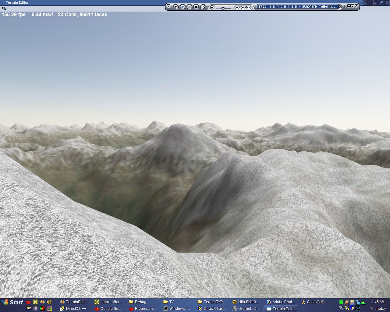
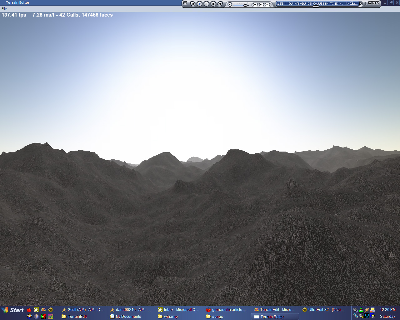
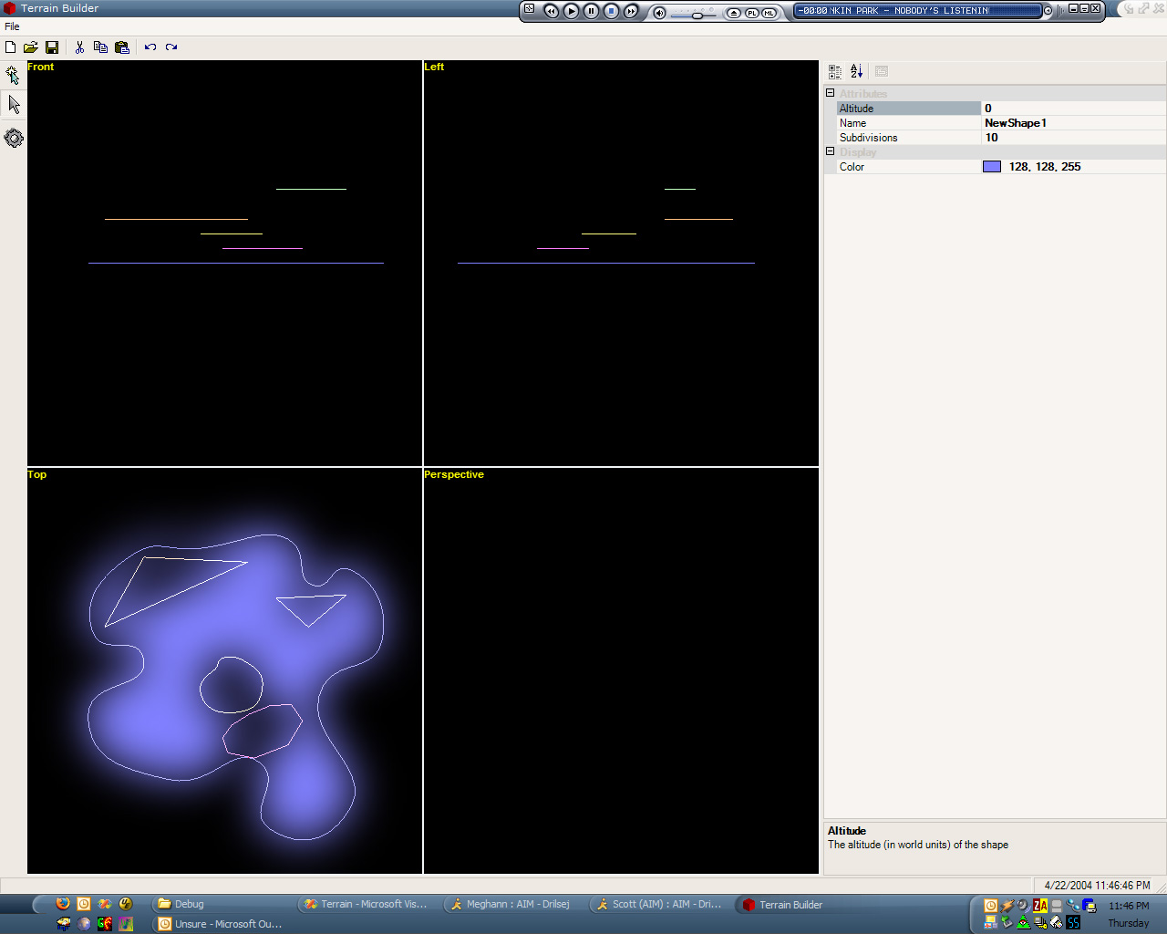
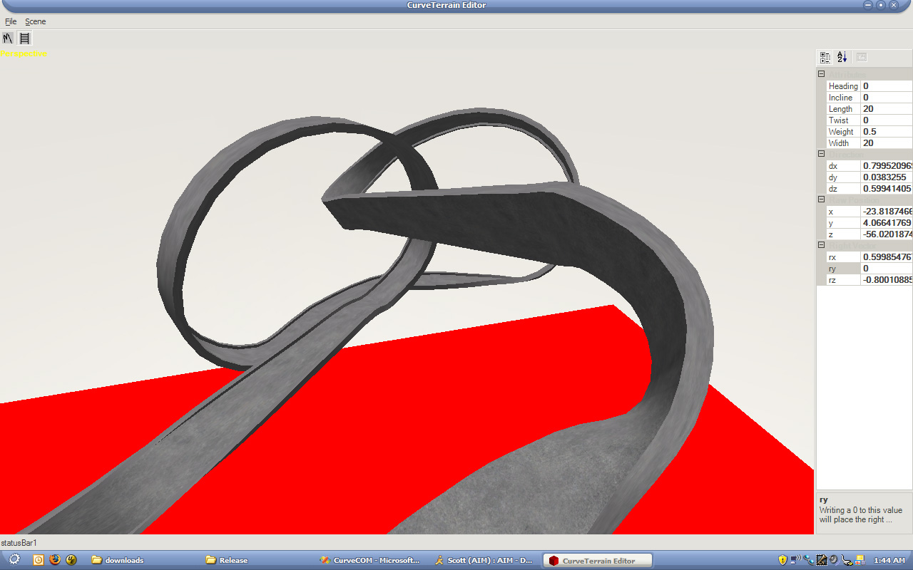
So when last we spoke, I had set my schedule. I had just a few short weeks to get a complete gameplay prototype running. So I started where every game developer seems to start: With the graphics.

I mentioned before that the graphics were simple. Polygonal, no textures. Writing that took about a day (very, very simple code). I checked it in on August 12th.

Next up: Input. No sense in gameplay if you can’t PLAY it. I took the input code that I wrote for my old NES emulator and modified it slightly for my new uses. That gave me automatic keyboard/joystick control.

Side note: Never initialize DirectInput after initializing Direct3D, because it does bad, bad things to the window interface. DirectInput subclasses the window, which Direct3D doesn’t like, so D3D doesn’t like to restore the state of the window correctly after doing a Reset (i.e. for switching between fullscreen/windowed).

Blah blah blah, wrote a bunch of stuff, got the gameplay test done. Only a few days behind schedule, on September 4th.

A Note on the Art Path

So, my original “art path,” as it were, was amazingly complex.
It kinda went like this:

  1. Create object in AutoCAD.
  2. Export from AutoCAD to .3ds
  3. Use a 3D modeling package to import the .3ds
  4. Manually fix up the incorrectly exported colors
  5. Export to .ase
  6. Run custom converter from .ase (an easily parseable ASCII file format) to my own mesh format.
  7. Profit!

This eight-hojillion step process was a pain and, moreover, had one fatal flaw in it.

Check out step number 3. AutoCAD was incorrectly exporting the object colors.

As it turns out, AutoCAD has the ability to set truecolor values to objects, but it also has a built-in 256 color palette (likely left over from the olden days). Now, when ACAD would export, instead of exporting my delicious true colors, it would export the nearest match in the color palette. Consequently, I had to fix them up later.

This became a problem when I tried to do my first test background – Fixing up all of the colors was way too time-consuming, so I had to find a better way.

FIRST I tried to import the DXF directly into the 3D modeler. However, it ALSO screwed up the import.
SECOND I tried to write my own DXF reader. As it turns out, the object that I’m using as my building block (the REGION) is one of the only TWO types of ACAD object that are encrypted in the DXF. Which is stupid.
THIRD I found a third-party program to convert REGIONs into PolyLines, which I WOULD be able to read. However, this program also dropped the same color information I was trying to preserve, thus ensuring that every last person in the universe has screwed up the color import/export with ACAD files.

The Solution!

I found out that AutoCAD has its own API for writing plugins called ObjectARX. Essentially, I downloaded it and wrote an export function from AutoCAD directly into my mesh format. It does the following things: Scan the scene for regions, and for each region it finds, triangulate it (using ear clipping) then write that to the file.

So now, my art path has become:

  1. Create object in AutoCAD
  2. Export directly to my mesh format, with correct colors intact.

Much better.

MEDIA!!!

I don’t have any new screenshots. What I *DO* have are two of the songs from the game.

The first one is the song that will play during the main menu on game startup. It’s the piano version of the main theme.

Piano of Destiny

The second is the first-level music, which IS the main theme (thus, both songs have the same melody).

Theme of Destiny

Anyway, it’s amazingly late and I work tomorrow, so that’s all I have time for today. Backgrounds truly begin tomorrow!

Concept of Destiny

So, the Four Elements V contest was announced in June. The rules are simple: Create a game, include the four elements:

  • Europe
  • Emblem
  • Economy
  • Emotion

Have it done by November 30th.

That said, I thought “well, those elements sound hard, screw that.” And I went along my merry way. Sometimes after that, I moved cross country and started a new job. But I had been watching the forums, and I noticed a few things:

Everyone seemed to go “I can do that! I’m making a…” followed either by “RPG” or “Strategy/Simulation game.” I began to think about what I could do that would be DIFFERENT from anything else in the competiton. It took a week or so before I came up with an idea, but I did:

Mop of Destiny: Lead the Palace of Westminster’s Caretaker, Jack Scroggins, on an epic battle against the advancing armies of The Shadow. It’s essentially a 2D action/platformer, along the lines of the original Castlevania games.

The four elements were as follows:

  • Europe – I set it in (and beneath) the Palace of Westminster, with the final level being a frantic climb up the turning gears inside of the clock tower colloquially known as Big Ben.
  • Emblem – At the completion of each level, Jack must touch the Emblem of Light. Each emblem is a seal on the gate to the Shadow Realm, and must be re-activated by Jack.
  • Economy – Again, at the completion of each level, a spiritual shopkeeper will appear, allowing the caretaker to purchase (or sell) special weapons and healing items using the souls of enemies vanquished along the way.
  • Emotion – Instead of being able to physically harm Jack, the Shadows can only cause him to become more afraid. As he becomes more afraid, his perceptions of the surroundings change (the world becomes a bit less colorful), and he recoils farther and farther in horror. If he becomes TOO afraid, he loses his sanity and becomes a shadow himself, and the game ends.

Since I was moving, I did not really have computer/Internet access, so I spent alot of time jotting notes and drawing concept sketches of various worlds. Initially, there were to be 8 levels (though this has been pared down to 6 for time), starting in the Palace of Westminster, taking Jack through the caves leading to the gateway into the Shadow Realm itself, then on a quick, frantic escape from the Shadow Realm, and finally up the clocktower to do battle with the Shadow King himself.

I determined what the big “problem areas” of gameplay would be, and decided to frontload most of them, to ensure that I knew that I had a chance of finishing. The main problem area had to do with the final level: Jumping from gear to gear would require some crazy collision detection and platform motion response. So that became the first goal: to get a “Control Test” working. This would have a bunch of platforms for the main character (represented by a fantastically drawn rectangle) to jump around on, including horizontal/vertically moving platforms and a spinning gear.

By this point, it was near the end of July, and I knew I had to get started. I initially started working on a basic level editor. I made a decision early on that the graphics would be 100% polygonal. Excepting the render targets, there is not a single texture in the entire game. This made the graphics code easy (all of the major graphics code was written in about a day), and made level editing easy (each vertex is a 2D position and a color). However, the level editor soon proved to be very complex – an interface that would allow me to do what I wanted would be a real pain to design.

I did some tests with some 3D modeling applications, and none of them were as simple to use as I’d like. However, my wife is an interior designer, and has AutoCAD, which proved to be amazingly simple. It was exactly the type of 2D model/level editor that I needed (with one major exception that I’ll talk about in a later post). Thus, I scrapped the whole editor I’d been working on and switched over to using AutoCAD.

By this point, it was mid-August. I needed to really get started, and I needed to get started fast; my design was very ambitious, so I needed to get working. My schedule was set as follows:

By the end of August, I wanted to have a gameplay test, complete with moving gears and working controls.

By the end of September, I wanted all of the major subsystems done. Sound, music, fonts, levels, animation, enemies, the HUD, the ability to walk to the next zone in the level, stuff like that.

By the end of October, I wanted to have the entire game playable (only no art assets would be done). You’ll see in a moment that this didn’t entirely happen (I ended up doing all of the character art in October, because making the actual enemies would have sucked without their art).

then, finally, it had to all be done by the end of November.

Currently it’s November 14th, and I have just completed my first complete playthrough of the game. None of the background art is done, and only 2 of the songs are done, but the game is playable. I have 16 days to do all of the art (I’m not an artist, really), and the music (I am, however, a composer), and the voice acting (which I can do), and the sound effects.

It’s going to be rough, but I think I can do it.

And now, to some SCREENSHOTS!

Keep in mind, of course, that I have not done any of the background art, so the screenshots kinda look like decent sprites running around on an Atari 2600 playing field, but the background art is going to start to get done soon.


Click to enlarge

Anyway, I’ll be continuing to post about the history of the project through when I (hopefully) finish it ontime for a victorious first place!

Long time, no update!

So, wow. It’s been what…over a year? How time flies when life is throwing buckets at you.

Well, I’m going to start updating this journal with information on the (currently) continuing development efforts of my 4e5 entry entitled Mop of Destiny.

No, I haven’t given up on that racing game. Content creation got the better of me, but it’s not a dead project. I figured I had a chance to FINISH a 4e5 entry, so I switched gears a bit.

More info to come shortly (tonight).

Our Continuing Mission…

It is now highly apparent that there is no chance of me finishing this project by the end of this month. It was an impressively unrealistic goal in the first place. Oh well. It did its intended job: To light a fire under me and make me get to work on it.

And I’m still working. I don’t really have any pretty screenshots of anything new, but I’ve just finished planning some extensions to the gameplay (a totally different method of doing the collision detection that’ll be faster, as well as different track cross-sections, like driving inside of a tube). Then I’ll start beefing up the actual graphics engine proper. It’ll be nice to get some actual environments around those tracks!

Modeling will go as follows:

  1. Use track editor to create track
  2. Export completed track to a mesh format
  3. Load mesh into standard 3D Modeling program
  4. Create background
  5. Save/export to some format that I can read in
  6. Replace the temp materials assigned in the modeling program with the actual in-game materials
  7. Run it through the lightmap-generating radiosity dealy
  8. Save as level format
  9. Profit!

Or something like that.

Sound complicated? It is! But it’s easier than me coding my own 3D modeller. I tried that once, it didn’t work out so well.

Anyway, the AI is coming along…slowly. I’ve stopped developing it until after the collision detection rewrite.

Anyway, I guess the release date has changed a bit. It’s now “When It’s Done.” Except I plan on that not becoming the Duke Nukem Forever version of “When It’s Done.”

This is still the most progress I’ve made on a game in my spare-time programming efforts. Ever. I’m happy with it!

Get Your Kicks On Loop 66

Finally! It took longer than expected (I had some issues with the collision detection), but I finally have the driving code working. That means, I can finally drive around these crazy tracks. As expected, because the tracks that I have were created before I even knew how the cars would handle or anything, not all of the turns/curves/loops are as forgiving as I’d like.

Some screenshots (note that the car is not actually going to be a sphere, but I needed something quick to represent the car):


Click to enlarge

Because the car is eventually going to be hovering, the driving control doesn’t have to be as accurate to real life as it would if the car had wheels. So I added some dampening to the sideways motion (Essentially lateral friction to keep the car from moving sideways, unless it’s skidding), but didn’t have to do a full-on friction model. Plus, the car has a force-field (or whatever they will call those things in the future), so the walls actually bounce the car more like a pinball bumper than in a realistic fashion (the force field applies some bounce force).

Anyway, now that I have the cars driving, it’s time for the next huge step: Driver AI.

Note that I have absolutely no idea at all how to write an AI to drive around my loopy sorts of courses. Time to do some research!

I’m Supposed To DRIVE on THAT?

Another week-plus break in journal entries. That’s starting to become a bad habit, but I don’t like updating when I don’t have anything to show.

Which brings us to today’s entry: I have something to show.

I created a new track editor. You may remember seeing screenshots of my previous track editor, way earlier in the journal. Those people who DO remember this are thinking to themselves, “That bonehead said that he would keep the existing editor because it works.” This is true. But, I decided that it was slightly hard (and by “slightly hard” I mean “nigh impossible”) to do some of the things that I really wanted to do fairly frequently (like spiral curves and full loops, to name a few). Plus, as the previous system was written using bezier patches , it took many patches to do any one feature (a loop generally took about 16-20 patches). This was lame.
>Since I am no longer using beziers as my basis for all terrain rendering, it’s no longer advantageous to use them exclusively in track creation. So I started over.


Click to Enlarge

Each track segment gets the following attributes (which are relative to the track segment’s initial orientation):

  • Length – This represents the angle of the track relative to the in-game representation of the north star. That, or just the length of the track down the middle. I can never remember which is which.
  • Width – Determines what the width will be by the end of the section of track (the previous section determines the initial width).
  • Curve – The amount of curvature of the track. A negative curve is to the left, positive is to the right. A 360 degree curve is, as expected, a full rotation.
  • Horizontal Skew – This is how much the track strafes to the side (along a sinusoidal sort of path) across its length. It’s like a lane-change. Only the pavement is changing lanes, not the car.
  • Incline Curve – This is the circular incline of the track. A 360 degree value of this would be a full loop. Positive is up, negative is down.
  • Vertical Skew – Similar to the horizontal skew, only vertical. How’s THAT for descriptive?
  • Twist – This is how much the track rolls to one side or the other along its length, which modifies the orientation for the next segment
  • Bank – This is similar to twist, except it raises one side instead of twisting around the middle, and the orientation remains unchanged in the next segment of track (this is to allow for banked curves, which I wouldn’t want to curve upwards because of the bank or something stupid like that).

Given those properties (And a semi-complicated way to combine them which I won’t detail here), I can still generate a track in segments. But I can use less segments to do the job.


Click to Enlarge

Once I got it generating, then I decided to make it considerably more adaptive. So it divides up the curves according to an error metric, which is why, in the last screenshot, some of the bits of track have fewer polygons (the straight bits only have one big one), and others have more.

The last thing to do is be able to export it to an actual mesh, so that I can load it up in a 3D modelling program and build the landscape around it.

But, for now, I can work on actually getting a car to drive on the track. Because now that I have a few levels, I want to find out what it’s like to drive on them!

WTS: Plane of +1 Infinity

So I finally got something interesting working. While there’s no pretty shading or even eye candy, what there IS is an infinite plane renderer, using a grid. The idea was to use this for water rendering, but there’s an easier and less complicated way to do it (a la Far Cry) that I’m going to use instead. I just thought I’d finish this up anyway because it’s moderately novel (at least, to me. Maybe it’s not.)
A few pictures of it in action (Hooray for poorly-compressed JPGs and their many artifacts!):


Click to Enlarge

What makes this interesting (to me at least, if nobody else) is that the visible portions of the plane are (for the most part) the whole visible bit of the plane. Also, the grid spacing is interpolated in post-projection space, so it’s a constant-ish LOD across the screen (which was to be a great help in rendering water waves with the detail in the near waves, but not the far waves).
Here are some pictures of it with the gridlines:


Click to Enlarge

Advantages:

  • With the exception of the four 4-component vectors used as shader constants, nothing is transferred to the card on a per-frame basis. The vertex/index buffers are completely static.
  • A very minimum of the grid is off-screen. Thus, the transformations are reserved for the on-screen objects only
  • With the screen-space linear interpolation of the grid, detail is concentrated where it’s needed.

Disadvantages:

  • Complex. Finding the best four points for the on-screen representation of the grid wasn’t quite as easy as I had initially thought. Especially since there are 5 and 6 edge cases.
  • The vertex shader is ever-so-slightly more complex than a normal shader. Just a few instructions, but every little bit, right?
  • It actually is quite difficult to make it handle the variations in height necessary for a water wave renderer. Actually, I haven’t done that part yet (and since I’ve found an easier way of doing the same thing, I probably won’t). That is left as an exercise for the reader.

How does it work, you ask? Okay, nobody asked that, but I’m going to tell you anyway. Because that’s what I do.

First up is the on-CPU setup. Given a plane in the 4-vector form of [a, b, c, d] (i.e. ax + by + cz +d = 0)

  1. Project the plane into post-projection space. To transform a plane using the 4×4 transformation matrix T, you multiply the 4-vector plane representation by the matrix Transpose(Inverse(T)). I decided to do the plane clipping in post-projection space because the clipping against the frustum is easier there (as it’s a box instead of a sideways headless pyramid).
  2. Get the vertices of the intersection between the frustum and the plane.
    • This intersection is the intersection of three planes: The two planes making up the frustum side, and the plane being rendered. However, since the planes of the frustum are axis-aligned planes in post-projection space, this can be simplified by substituting in the two known components (from the frustum planes) for that edge and solving for the third variable. For instance given the upper-left corner (x = -1, y = -1), z = -(a*x + b*y + d)/c.
    • Once you have the third component, check to make sure that it is within the valid half-cube range (Note: in Direct3D, visible post-perspective space is within the half-cube where x is in [-1, 1], y is in [-1, 1] and z is in [0, 1]). If it IS in range, add it to the list of edge points.
    • There can be at most six points generated by this set of checks (giving one polygonal edge per frustum plane. 6 edges = 6 points, see?)
  3. Ensure a clockwise winding order for the points. I used the gift-wrap sort of method, starting at the point nearest the screen, do a 2D check (ignore Z) to find the “most clockwise” point along the way (i.e. the point at which, given the line between the current point and the next point, all vertices are to the right of that line).
  4. This is the complicated part. We need to get the number of points to exactly 4 (as what the shader is expecting is a quad)
    • Given 3 points, duplicate the one nearest the camera.
    • Given 5 points:
      • Find the diagonal edge that crosses from one side to an adjacent side (i.e crosses from the top side to the right side, as opposed to left to right)
      • Look at the intersection between that diagonal line and the two sides that it currently doesn’t touch.
      • Choose the side that has the intersection point nearest the screen, and extend the corresponding point along the diagonal to the intersection point
      • At that point, along the edge where that intersection was, there are now three collinear points. Remove the one in the middle, which brings the total down to four points
    • Given 6 points:
      • There are two diagonals that cross from one side to an adjacent one, so we’ll pick the one that represents the far plane intersection (the z coordinate of both of the points on this diagonal will be 1).
      • That diagonal gets extended to both of the sides that it doesn’t touch, similar to the 5-point case. Except that it extends both directions instead of just the one.
      • Remove the two redundant vertices
  5. Send the 4 points to GPU (I pass them in in the world matrix slot, since they’re 4 float4 values).

Okay, that was the worst of it. Now there’s the GPU-side bits:

  1. The mesh input is a grid of u,v coordinates ranging from 0 to 1. Linearly interpolate between the four post-projective planar intersection points passed in from the CPU using the u,v values. worldSpace = lerp(lerp(inMatrix[0], inMatrix[1], in.u), lerp(inMatrix[3], inMatrix[2], in.u), in.v) The 3 and 2 are in that order because the vertices are given in clockwise order.
  2. Using the inverse viewproj matrix, project these points back into worldspace.
  3. The worldspace x and z can be used as texture coordinates (scaled, if you want. I use them verbatim right now).
  4. Reproject the worldspace coordinates back into projected space. This is necessary because the linearly interpolated points are not perspective-correct (causing the texture mapping to totally flip out. It was like a bad flashback to the original Playstation. I do not wish that upon others).

Math-heavy? Yep.
Poorly explained in this post? Probably.
Able to be cleared up by questions in the comments section? You betcha.

Hope this has been informative (though it’s more of a dry read than I would have liked).

Future Intrigue vs. the Wasteland of the Now

I promise that one day this journal will have something more entertaining than my I’m-Planning-On-Making-This-Cool-Game ramblings. In the interim, I present to you my general (and likely highly incomplete) plan of action (not including creation of art/level/music/sound assets, which will sort of happen as necessary):

  1. Get the graphics engine to the point where it can display a level, though without the greatest of visual quality (probably simple directional lighting, crap texturing, nothing that will make a pretty screenshot. It won’t look pretty, but it’ll work).
  2. Implement the driving-on-track code (i.e. keeping the vehicle on the track, bouncing/sliding against walls, controlling the vehicle)
  3. Implement some form of AI for the opponent cars. At this point, the game will be “playable” in a weak sense
  4. Begin implementation on the sound/music code. Get basic engine sounds, collisions, etc working.
  5. Begin to improve the graphics engine, by implementing the lightmap generator, getting new shaders written, particle systems, etc. Add some polish
  6. Begin work on the menuing system. Get a title screen/etc.
  7. Work on enemy AI. Make it drive better, make it tuneable (i.e. difficulty levels).
  8. If I’m going to do network code, I’ll probably want to start work on it right around here
  9. Start polishing the sound engine a bit (Add ability to have ambient sounds in the levels, doppler effect, all sorts of other audible cues)
  10. Get the graphics engine to the point that no more code changes will be necessary
  11. Begin fleshing out levels, start chaining them together into circuits
  12. More polish. Make the menus look cooler, tweak performance, all of that jazz
  13. At this point, the game will be highly playable, so anything past this is pure candy. HDR rendering? motion blur? If there’s time.

There are also some considerations that I will be attempting to make over the course of the whole development:

  • The game needs to be, above all else, fun. If I’m not having fun playing it, then why should I even be making it?
  • I am going to try my hardest to minimize load times. That is a very big priority for me. I hate waiting for games to load.
  • The driving control will be simple and easy. I have a great idea for mouse-driven steering (which may or may not be original, but I haven’t seen it personally) that I prototyped a while back…It’s definitely fun, but it needs tweaking. Probably in the form of a control options screen, with a good default setting.
  • The graphics code should be easily extendable. I’d like to be able to add higher-quality versions of the existing effects in the future (i.e. add some PS3.0 support for full-scale displacement mapping or such).

Hm. For the three of you out there that happen to keep tabs on this journal, if you see something (rather, fail to see something) important that I’m missing, please let me know. I’m new to this whole actually-trying-to-FINISH-a-game-in-this-lifetime thing.

The story thus far…

One Point Five Years Ago

Early last year, I was playing around with a simple terrain engine. It was your basic height-field based terrain engine. It was also crap-tastic. But hey, you’ve gotta start somewhere. Thus, I started with this:


(Click To Enlarge)

Kinda lame, but it was a good test. Each chunk was LODified by using a Binary Triangle Tree, which was a great simplification method, though I did eventually switch to using progressive meshing (though leaving the edges in-tact…not the greatest LOD scheme ever). It was then that I had a vision. Well, not so much a vision, but an idea. Well, not even an idea. More of a thought. Cliffs! That’s right, cliffs. And caves. Those were two things that I would love to have, but they’re impossible with a straight-up heightfield renderer. So I set my tired code aside, and began my next crazy scheme.

Terrain Idea The Second!

So, I thought: what if I could model a level in a manner similar to making a topographical map. Something like this:


(Click To Enlarge)

In this system, each shape could be drawn, and given a height value. The editor would fill in the drawn shapes with polygons, connecting them to the other inner shapes (and outer shapes), adding slopes when asked (or making a given shape a plateau).

Sound crazy? It was. I coded it for about three months, working on logic to triangulate a complex polygon (overlapping not allowed) which contains children (which are holes in the parent polygon). Then I worked on smoothing the polygons by adding curves (see the first two screenshots for a comparison). Each edge was essentially a bezier curve, where the middle two control points were placed based on the angle of the connection to the next/previous line segments.

Now, right about now, you may be thinking to yourself: “How does this solve the problem of caves? How did you handle the LOD switching? Isn’t this a lot of work? What’s the meaning of life?” To answer your questions, in order: It doesn’t, I didn’t, Way too much, and free beer. This particular concoction was way too complex, and not near enough to what I wanted. So it, too, was scrapped.

The Not So Distant Past, Or: How to Totally Copy SSX’s Idea

I started browsing the web for other creative ways to generate terrain. It was then that I came upon THIS article. What a brilliant idea, I thought! Use curved surfaces to model terrain! So I started work on Terrain III: Terrain With a Vengeance. Not too long afterwards, I had a decent curved-surface terrain. The beziers were calculated in a vertex shader, given the matrix representation of the surface as a 4×4 matrix. Each vertex buffer simply contained the u and v coordinates (in the range [0, 1]) for the patch of the given resolution (different vertices in the vertex buffer were used for different tesselations). However, there were two big problems:

  • The vertex shader was somewhat slow, with the extra matrix multiplications (three 4×4 multiplications and a dot product for position alone)
  • There were cracks between the patches, due to floating-point rounding errors.

So, I thought, what if I calculated the patches in software in a big dynamic vertex buffer, using a better method? I ended up using de Casteljau’s Method on the edges of the patches, because it does not have the same floating-point issues that the matrix representation does. However, I continued using the matrix method on the interior points, for speed reasons. Each patch was cached into the vertex buffer using a cheap LRU cache. This eliminated the “sparkles” caused by the floating-point errors, and significantly improved my framerate. And now, screenshots:


(Click To Enlarge)

This method worked well, but there were issues with locking/unlocking the buffer. Also, 800 patches meant 800 DrawPrimitive calls, which is, how you say, lame. Thus, I rebuilt the cache algorithm (Yes, I have the technology) to cache items into a set of smaller vertex buffers (that I called “slices”), which were each bound to a specific material (i.e. grass, etc). Thus, they could be batched up better. Soon, 800 patches meant only about 30 draw primitive calls. Which was way better, but there was still a problem. With great caching comes great framerate instability. Since the caching algorithm would sometimes not have to do anything, but sometimes it would have to cache a lot of patches, the framerate became very unstable. Even though it was running faster than 100 fps almost the entire time, it was still highly visible stuttering (especially when I fillrate-limited it a bit). Plus, there became the question of how to actually MODEL such a terrain (I was going to have to write a super-complicated terrain editor). So I wavered. It seemed that there were many, many problems with this implementation and that, while it’s definitely cool, I don’t know that I’m going to be able to do what I want within my newly-created timeframe. So I decided to set this method aside as well, and move on.

The Present, But Not the Birthday Kind

And that brings us to now. I’ve decided that I’m going to use a simple mesh format for the terrain, though with LOD data built into it. That way, I can use an existing modeling program (I’m looking at you, Blender) to do the modeling, build some simple texture/material/atmosphere editing utilities (or one texture/material/atmosphere editing utility), and just use that. Break it up into LOD-able chunks, and I think I have a winner!

Also, I’ll probably keep the track editing interface that I already have (though I’ll have to improve on it, obviously, since it’s…clunky, at best). But it provided me with these:


(Click To Enlarge)

Which are fairly representative of the types of tracks I’m aiming to have.

Alright, class, that’s the end of your history lesson for today. Up next: New developments in code!